Laser Processing Apparatus and Laser Processing Method

a laser processing and laser processing technology, applied in metal-working equipment, welding equipment, manufacturing tools, etc., can solve the problems of time elapsed and general uneven laser beams

Inactive Publication Date: 2009-02-05
PHOETON CORP
View PDF11 Cites 62 Cited by
  • Summary
  • Abstract
  • Description
  • Claims
  • Application Information

AI Technical Summary

Benefits of technology

[0058]As described above, the laser processing apparatus and the laser processing method in accordance with the present invention include the focusing or imaging means and the arranging means for the subject to be processed, and are configured so that the arranging means is controlled so as to perform predetermined movement with respect to the laser beams to uniformize the processing diameter or the processing shape of the portion to be processed formed in the subject to be processed.
[0059]Further, by providing the mechanism for relatively shifting the focusing or imaging means and the arranging means for the subject to be processed, the portion to be processed can be processed into an arbitrary shape.
[0060]Further, the laser processing apparatus and the laser processing method in accordance with the present invention include two independent beam expander mechanisms that change the beam sizes of laser beams in two directions intersecting at right angles in the vertical plane with respect to the laser beams and make the principal rays parallel, and can align the divergence angles of laser beams, by which the processing diameter or the processing shape of the portion to be processed formed in the subject to be processed can be uniformized.
[0061]Also, the laser processing apparatus and the laser processing method in accordance with the present invention have the zoom mechanism in at least one expander mechanism. Therefore, even when the magnitude of the divergence angle of laser beams changes with time, the divergence angle of laser beams incident on the focusing or imaging means is kept constant by the zoom mechanism, so that the processing diameter or the processing shape of the portion to be processed formed in the subject to be processed can be uniformized.

Problems solved by technology

When processing is performed by the aforementioned microlens system, a disadvantage that the laser beams are generally uneven at the early stage or when time has elapsed has been known.

Method used


Image

  • Laser Processing Apparatus and Laser Processing Method
  • Laser Processing Apparatus and Laser Processing Method
  • Laser Processing Apparatus and Laser Processing Method

Examples


example 1

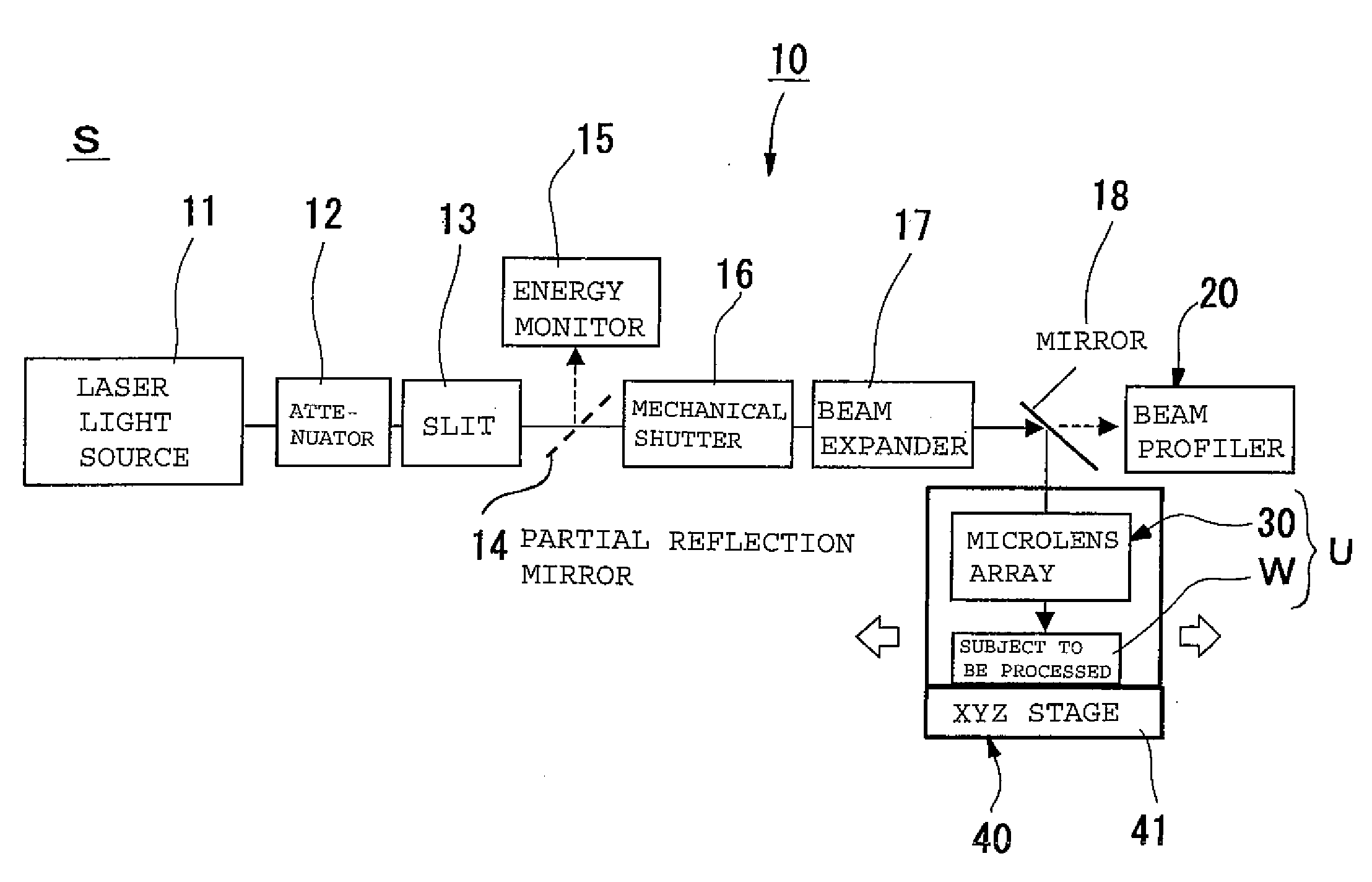
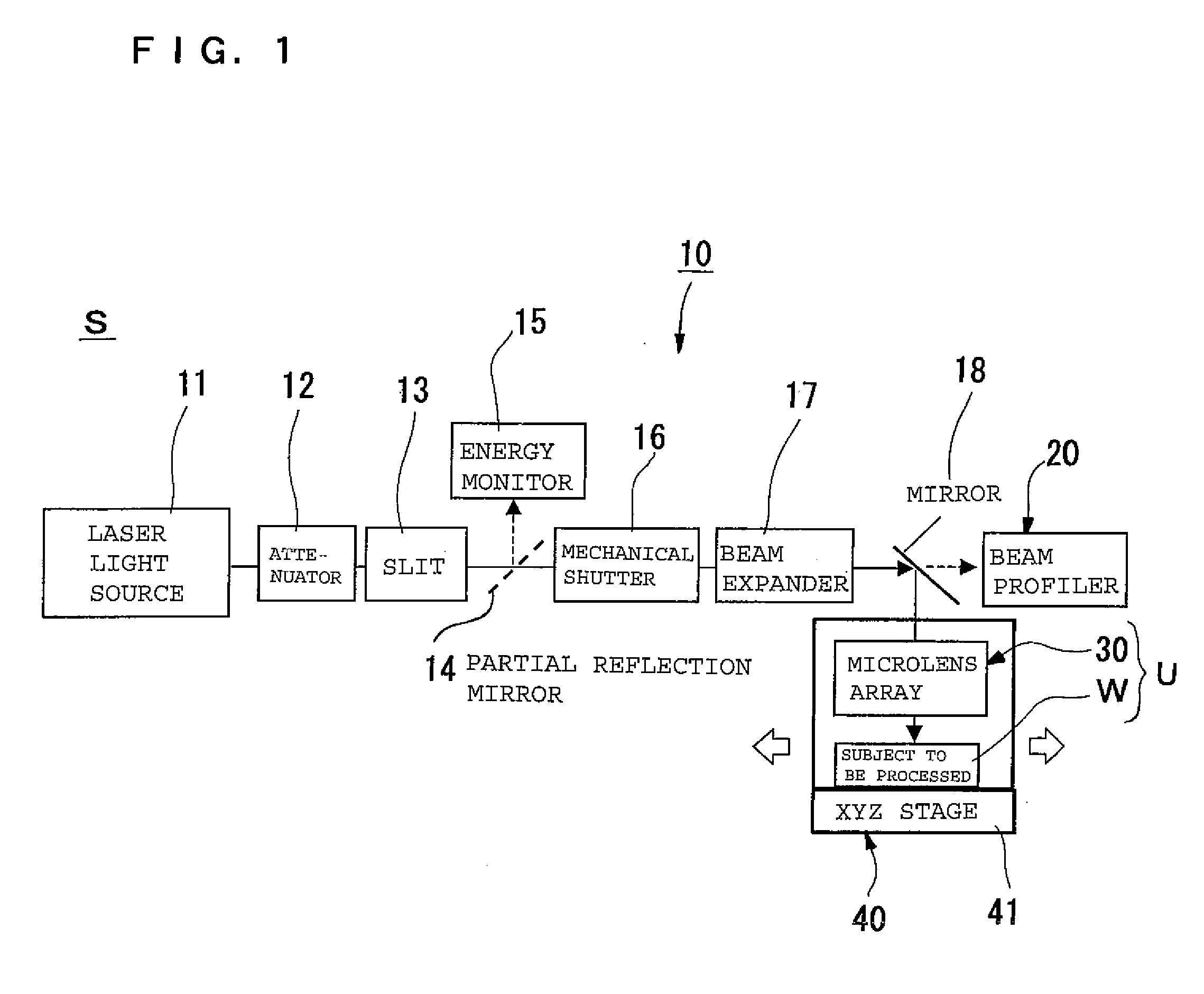
[0124]As shown in FIG. 1, a laser processing apparatus S of this embodiment includes a laser device 10, a beam profiler 20, a microlens array 30 serving as a focusing means, and a work adjusting means 40, which is an arranging means for a subject W to be processed. A unit U is formed by a microlens array 30 arranged over the work adjusting means 40 and the subject W to be processed.

[0125]The laser device 10 of example 1 includes a laser light source 11, an attenuator 12, a slit 13, a partial reflection mirror 14, an energy monitor 15, a shutter (mechanical shutter) 16, a beam expander 17, and a mirror 18.

[0126]The laser light source 11 emits laser beams according to the control of a control section, not shown, and sends the laser beams to the beam expander 17 via the attenuator 12, the slit 13, and the shutter 16. The laser beams passing through the slit 13 are partially reflected by the partial reflection mirror 14, and are guided to the energy monitor 15. The energy monitor of thi...

example 2

[0211]FIGS. 18 and 19 show the laser processing apparatus S in accordance with example 2. The laser processing apparatus S in accordance with example 2 is configured so that a rotary table 42 is provided on the stage 41 as the work adjusting means 40 for the subject W to be processed in the same configuration as that of example 1.

[0212]In this example, as shown in FIG. 18, the unit U in which the microlens array 30 and the subject W to be processed are integrated scans the beam area B by changing the angle with respect to the optical axis direction of irradiation beams.

[0213]As one of the characteristics of the excimer laser etc., the divergence angle of laser beam is sometimes changed by the time change of laser. In this case, the change usually occurs anisotropically in the longitudinal and transverse directions. Therefore, the processing point has a tendency to change into an elliptical shape.

[0214]However, in the configuration as shown in this example, since the unit U rotates, ...

example 3

[0215]FIGS. 20 and 21 show the laser processing apparatus S in accordance with example 3. The laser processing apparatus S in accordance with example 3 is configured so that the configuration except the mirror 18 and the beam profiler 20 is the same as that of example 1, and a mirror scan unit 50 is provided in the configuration of example 1. The configuration of the mirror scan unit 50 is shown in FIG. 21. The mirror scan unit 50 includes a first mirror and a second mirror 52.

[0216]The first mirror 51 reflects light from the upper direction toward the lower direction in FIG. 21, and the second mirror 52 reflects light from the paper top surface direction toward the paper back surface direction in FIG. 21.

[0217]The first mirror 51 and the second mirror 52 can move in the respective arrow-mark direction in FIG. 16.

[0218]By driving these mirrors in association, scanning can be performed two-dimensionally over the microlenses 31.

[0219]However, for the moving mirror, mechanical angle fl...


PUM

PropertyMeasurementUnit
areaaaaaaaaaaa
optical axisaaaaaaaaaa
sizesaaaaaaaaaa

Abstract

A laser processing apparatus for processing a multitude of portions to be processed in an area to be processed in a subject W to be processed, including a laser device, a focusing or imaging means for laser beams provided by the laser device, and an arranging means for arranging the subject W to be processed, in which the subject W to be processed and the focusing or imaging means are fixed, and the subject to be processed is processed while relatively shifting the laser beams and the focusing or imaging means so that the focusing or imaging means is irradiated from different areas in the laser beam, inside and outside the area to be processed, and that cumulative laser beam irradiation time during the processing of each of the multitude of portions to be processed is equalized.

Description

TECHNICAL FIELD[0001]The present invention relates to a laser processing apparatus and a laser processing method and, more particularly, to a laser processing apparatus and a laser processing method for performing many kinds of processing collectively on a subject to be processed by applying laser beams.BACKGROUND ART[0002]When a subject to be processed is drilled by applying laser beams, pulse irradiation of laser is performed many times on a subject to be processed, or processing is performed by irradiation for a fixed time.[0003]In this process, multiple points collective processing (hereinafter referred to as a “microlens system”) has been known in which a laser beam is branched into a multitude of beams by using a microlens array, and is condensed on a surface to be processed, by which many holes are formed in the subject to be processed.[0004]When processing is performed by the aforementioned microlens system, a disadvantage that the laser beams are generally uneven at the ear...

Claims


Application Information

Patent Timeline
Patent Type & Authority Applications(United States)
IPC IPC(8): B23K26/00B23K26/16B23K26/08
CPCB23K26/067B23K26/08B23K26/073B23K26/0676B23K26/40B23K26/064B23K26/082
Inventor ANDO, SATOSHIMURAOKA, TOMOBUMINIRE, TAKASHIMATSUNO, AKIRAKURATA, TADASHI
Owner PHOETON CORP
Why Eureka
Try Eureka