
Cooking apparatus and method of controlling the same

a technology of cooking apparatus and control method, which is applied in the field of cooking apparatus, can solve the problems of increasing the manufacturing cost of the oven, increasing the structure and control of the oven, increasing the cooking time and power consumption, etc., and achieves the effect of reducing the temperature change in the cooking chamber

Active Publication Date: 2009-02-05
SAMSUNG ELECTRONICS CO LTD
View PDF1 Cites 23 Cited by
  • Summary
  • Abstract
  • Description
  • Claims
  • Application Information

AI Technical Summary

Benefits of technology

[0014]It is another aspect of the invention to provide a cooking apparatus to reduce the temperature change in a cooking chamber and a method of controlling the same.
[0026]Typically, the airflow adjusting unit controls the opening degree of the upper ventilation holes or the lower ventilation holes formed at the fan cover to adjust the amount of heated air supplied into the cooking space.
[0029]Generally, the method further includes determining whether the temperature of the second cooking chamber has reached the target temperature, when the temperature of the second cooking chamber is higher, by a predetermined level, than the target temperature, controlling the airflow adjusting unit to decrease the opening degree of the ventilation holes communicating with the second cooking chamber, and, when the temperature of the second cooking chamber is lower, by the predetermined level, than the target temperature, controlling the airflow adjusting unit to increase the opening degree of the ventilation holes communicating with the second cooking chamber.

Problems solved by technology

Consequently, the cooking time and power consumption are increased.
As a result, the structure and control of the oven are complicated, and the manufacturing costs of the oven are increased.
Consequently, the temperature in the cooking chamber greatly fluctuates, with the result that the cooking efficiency is lowered when cooking food necessary to be maintained at a fixed temperature.

Method used


Image

  • Cooking apparatus and method of controlling the same
  • Cooking apparatus and method of controlling the same
  • Cooking apparatus and method of controlling the same

Examples


Embodiment Construction

[0045]Reference will now be made in detail to the embodiment of the present invention, examples of which are illustrated in the accompanying drawings, wherein like reference numerals refer to like elements throughout. The embodiment is described below to explain the present invention by referring to the figures.

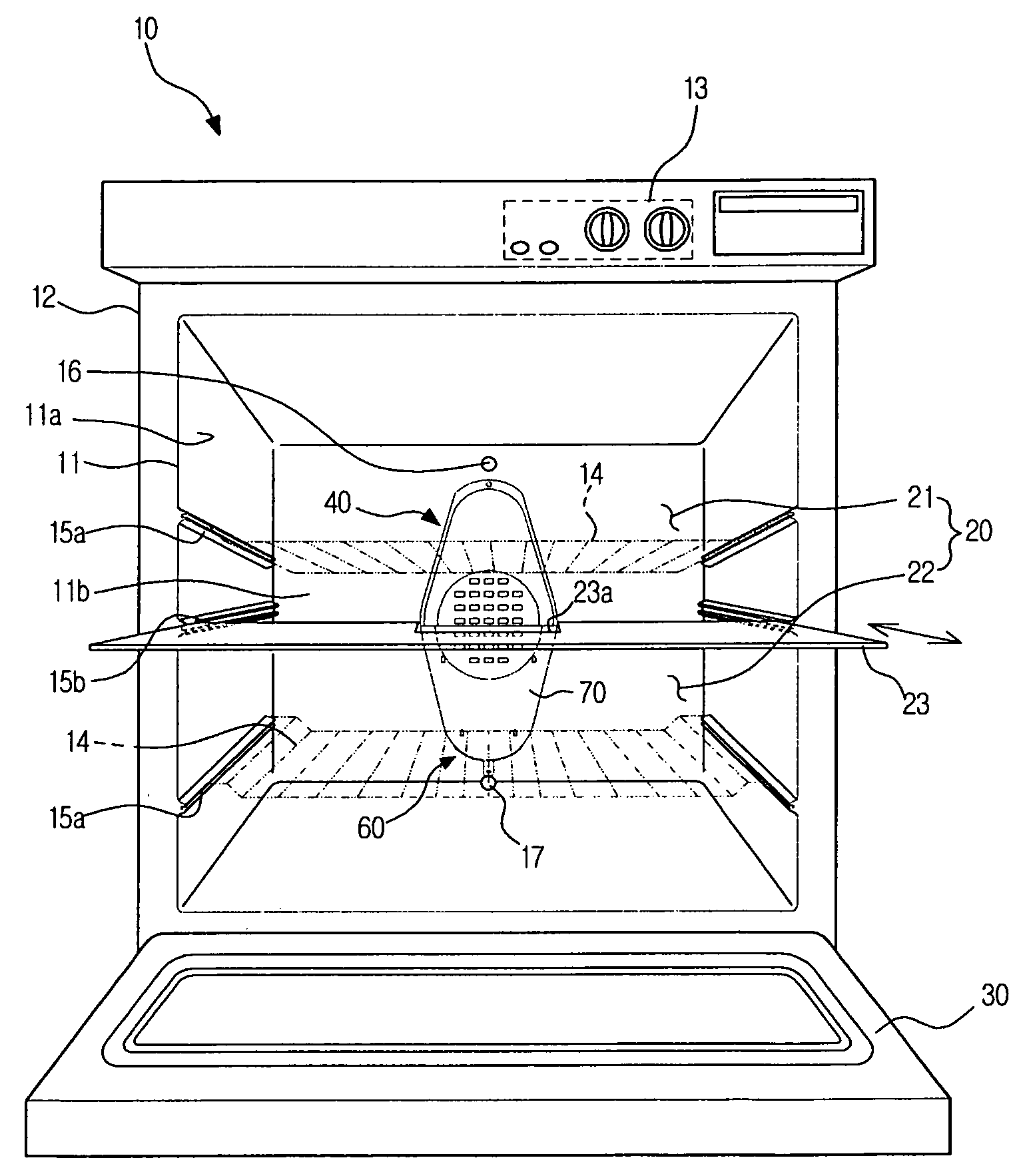
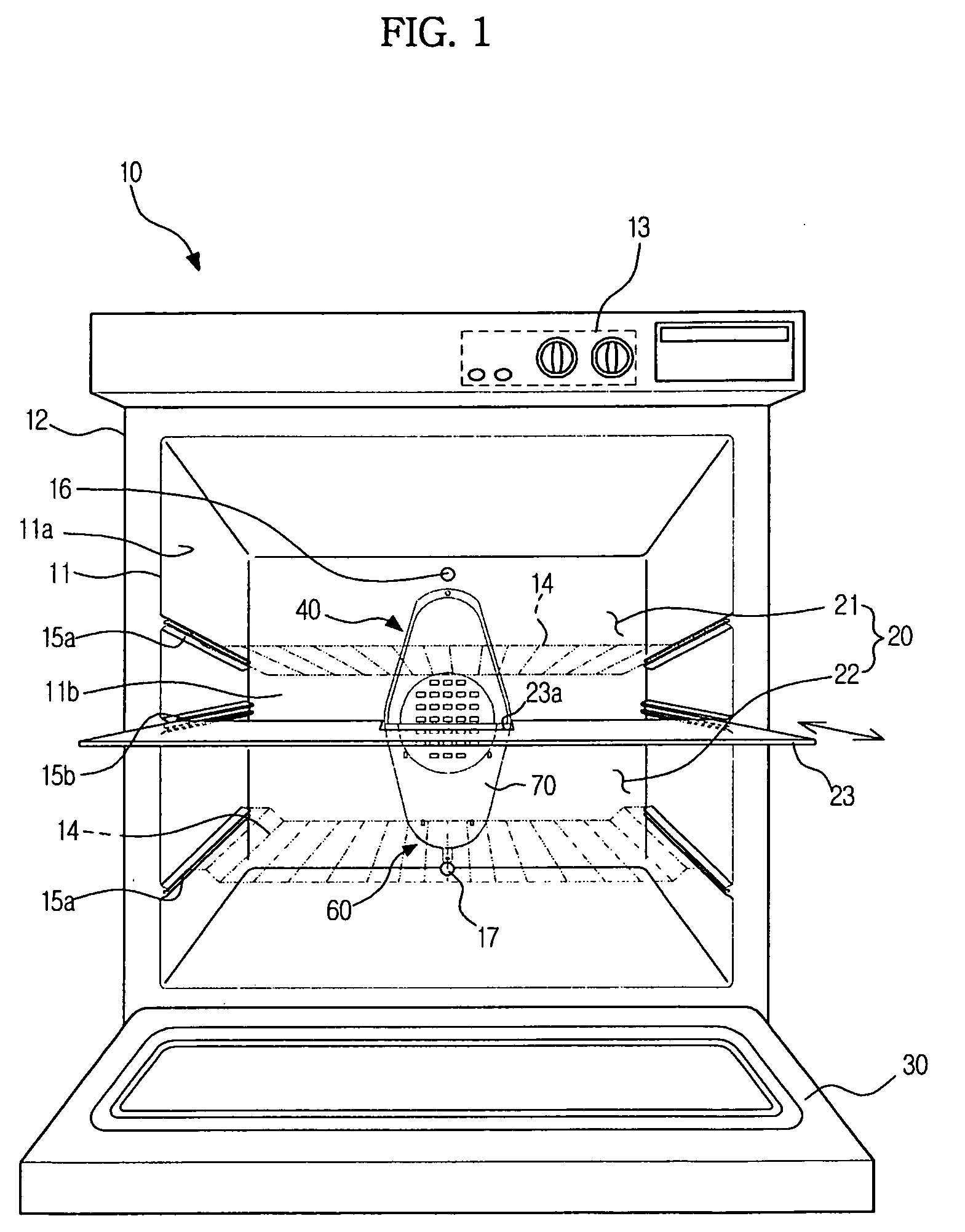
[0046]FIG. 1 is a perspective view schematically illustrating the structure of a cooking apparatus according to an embodiment of the present invention.

[0047]As shown in FIG. 1, the cooking apparatus includes a main body 10 open at the front thereof and having a cooking chamber 20 defined therein, a door 30 hingedly mounted to the front of the main body 10 to open and close the cooking chamber 20, a divider 23 detachably mounted in the cooking chamber 20 to divide the cooking chamber 20 into a plurality of cooking spaces, a heated air supply unit 40 to supply heated air into the cooking chamber 20, and an airflow adjusting unit 60 to adjust the flow of heated air supplied to t...


PUM


Abstract

A cooking apparatus and a method selectably cook food using one or more of a plurality of cooking spaces formed by a divider while using a same heat source and control different temperatures of the cooking spaces formed by the divider. An embodiment of the cooking apparatus includes a cooking chamber, a divider to divide the cooking chamber into cooking spaces, a heated air supply unit including a fan cover having upper and lower ventilation holes, a detection unit including temperature sensors to detect the interior temperatures of the cooking spaces, an airflow adjusting unit to adjust an amount of heated air supplied, and a control unit to control the amount of heated air, based on an interior temperature of the cooking space, to adjust a temperature to a target temperature set by a user.

Description

CROSS-REFERENCE TO RELATED APPLICATIONS[0001]This application claims the benefit of Korean Patent Application No. 2007-76993, filed on Jul. 31, 2007 in the Korean Intellectual Property Office, the disclosure of which is incorporated herein by reference.BACKGROUND[0002]1. Field[0003]The present invention relates to a cooking apparatus, and, more particularly, to a cooking apparatus that cooks food using a blowing fan.[0004]2. Description of the Related Art[0005]Generally, a conventional convection type cooking apparatus includes a heater energized to emit heat, an oven cavity in which food is cooked by heat emitted from the heater, a blowing fan mounted in the oven cavity to circulate air in the oven cavity by convection, convection inlet holes mounted at the rear of the cavity to suction the air circulated by the rotation of the blowing fan, convection outlet holes mounted at the rear of the cavity to discharge the air circulated by the rotation of the blowing fan, and a plurality o...

Claims


Application Information

Patent Timeline
IPC IPC(8): A21B1/26
CPCF24C15/322F24C15/18F24C7/082F24C15/006
Inventor KIM, TAE WOOHONG, SEIJ WEONSHON, JONG CHULLKIM, HYANG KI
Owner SAMSUNG ELECTRONICS CO LTD
Learn More