Mass-analysis method and mass-analysis apparatus

Inactive Publication Date: 2009-02-05
SHIMADZU CORP
View PDF9 Cites 28 Cited by
  • Summary
  • Abstract
  • Description
  • Claims
  • Application Information

AI Technical Summary

Benefits of technology

[0039]The mass-analysis method and apparatus according to the first and second aspects of the present invention can generate product ions with a high dissociation efficiency during the CID operation and assuredly capture the product ions within the ion trap while preventing the dissipation of product ions having small mass-to-charge ratios. Therefore, the

Problems solved by technology

However, it is practically difficult for AITs to change the frequency Ω. Therefore, the amplitude V is usually changed to regulate the LMC value.
However, increasing the q-value also increases the LMC value and thereby makes it more difficult to trap product ions resulting from dissociatio

Method used


Image

  • Mass-analysis method and mass-analysis apparatus
  • Mass-analysis method and mass-analysis apparatus
  • Mass-analysis method and mass-analysis apparatus

Examples


Embodiment Construction

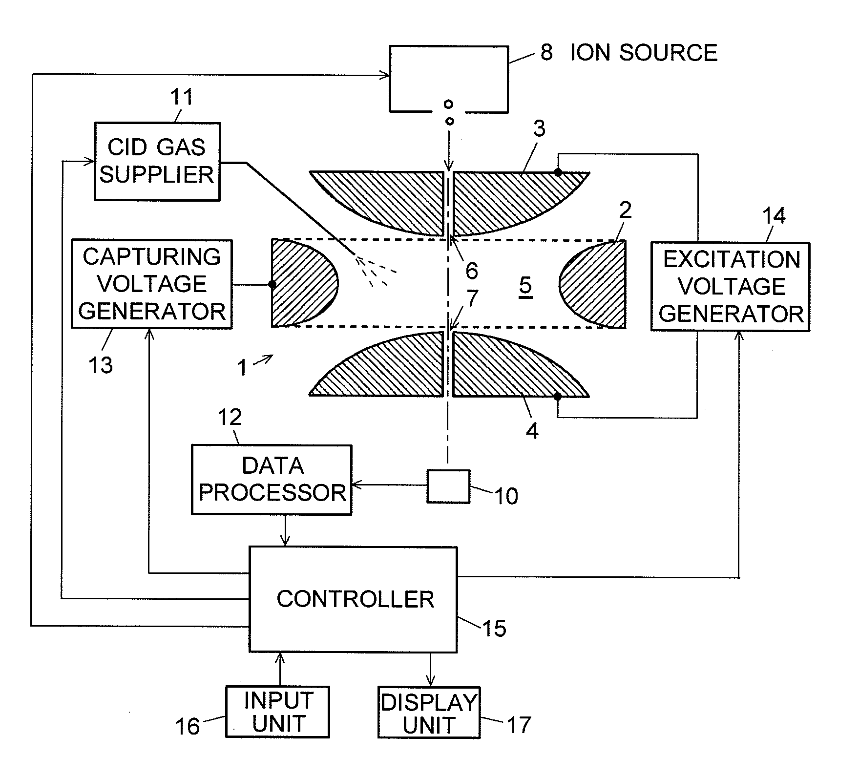
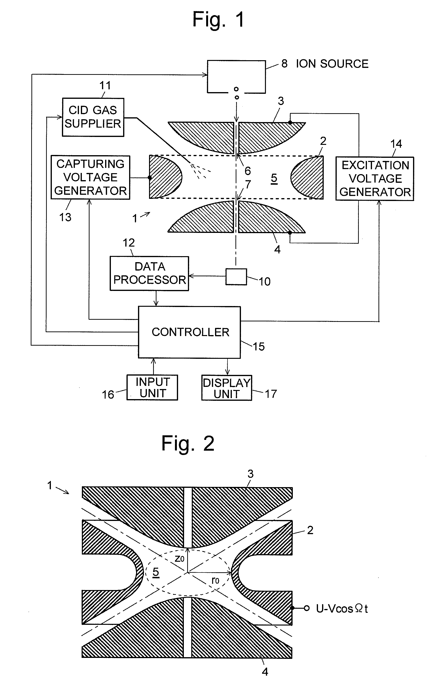
[0048]This section details the structure and operation of an ion trap mass spectrometer (IT-MS) as an embodiment of the second aspect of the present invention for carrying out the mass-analysis method according to the first aspect of the present invention. FIG. 1 is a general configuration diagram of the IT-MS of the present embodiment. The components of the ion trap are denoted by the same numerals as already used in FIG. 2.

[0049]As explained previously, the ion trap 1 includes a ring electrode 2 and end-cap electrodes 3 and 4. The ring electrode 2 is connected with a capturing voltage generator 13, while the end-cap electrodes 3 and 4 are connected with an excitation voltage generator 14. An ion source 8 is located outside the injection port 6 formed approximately at the center of the inlet end-cap electrode 3. Molecular ions generated by the ion source 8 will be introduced through the injection port 6 into the ion-trapping space 5. The exit end-cap electrode 4 has an ejection por...


PUM


Abstract

Among various ions introduced into an ion trap 1, those ions which are within a predetermined mass range including the mass-to-charge ratio of an objective ion are selected. Then, the frequency of a capturing voltage is set so that the objective ion will be captured with a high q-value, and a CID gas is introduced into the ion trap 1. An excitation voltage corresponding to the mass-to-charge ratio of the objective ion is applied to end-cap electrodes 3 and 4 to cause an oscillation of the objective ion and help dissociation of the ion by CID. The high q-value leads to a high dissociation efficiency. The application of the excitation voltage is discontinued before the low-mass ions produced by CID totally dissipate. Simultaneously with this operation, or slightly delayed therefrom, the frequency of the capturing voltage is switched so that the q-value will be lowered. Although the high q-value allows the low-mass product ions to easily dissipate during the CID process, they can be captured within an ion-trapping space 5 since the q-value is lowered when those ions still remain there. Thus, measurement of low-mass product ions can be simultaneously achieved with improvement of dissociation efficiency.

Description

TECHNICAL FIELD[0001]The present invention relates to a mass-analysis method and mass-analysis apparatus in which an ion to be analyzed is dissociated by collision-induced dissociation using an ion trap for confining ions by an electric field.BACKGROUND ART[0002]In the field of mass spectrometry, a technique called the MS / MS analysis (or tandem analysis) is widely known. Generally, an MS / MS analysis is conducted as follows: Initially, an ion having a specific mass-to-charge ratio (m / z) is selected from various kinds of ions generated from an object to be analyzed. Then, the selected ion, which is called the precursor ion, is dissociated into product ions by an appropriate process, e.g. collision-induced dissociation (CID). The product ions thus created are subjected to mass analysis to obtain information about the molecular structure of the objective ion. In the case of ion trap mass spectrometers, the CID process can take place within an ion trap having the function of confining io...

Claims


Application Information

Patent Timeline
IPC IPC(8): B01D59/44
CPCH01J49/0063H01J49/424H01J49/0081
Inventor FURUHASHI, OSAMULI, DING
Owner SHIMADZU CORP
Why Eureka
Try Eureka