Lid opening/closing system for closed container and substrate processing method using same

a closed container and substrate technology, applied in the direction of pile separation, transportation and packaging, packaging goods types, etc., can solve the problems of significant increase in the interior pressure of the pod, oxidized surface of the wafer, and inability to achieve the desired characteristics of miniaturized elements, etc., to achieve the effect of reducing the amount of oxidizing gases diffusing from the mini-environment, simple structure and reduced volum

Active Publication Date: 2009-02-05
TDK CORPARATION
View PDF10 Cites 36 Cited by
  • Summary
  • Abstract
  • Description
  • Claims
  • Application Information

AI Technical Summary

Benefits of technology

[0014]In the above described lid opening and closing system, purges nozzle that can supply a gas in a direction toward the interior of the storage container may further be provided outside side edges of the first opening portion in the second mini-environment. In the case where such a purge nozzle is provided, it is preferred that the direction of gas supply by the purge nozzle be substantially parallel to a plane that extends perpendicularly to the direction of gas supply from the curtain nozzle and toward a certain point equidistant from the purge nozzles in the plane. Furthermore, in the above described lid opening and closing mechanism, the door may substantially close the second opening portion by its flat surface opposite to the surface that closes the first opening portion. In this case, the flat surface or a member embedded in the flat surface may be adapted to come in contact with a portion of the enclosure defining the second opening portion around it to enhance the degree of closure of the second mini-environment. The above described lid opening and closing system may be designed in such a way that the door is swung from a position at which it closes the first opening portion upon substantially closing the second opening portion, and the gas supplied from the curtain nozzle can be introduced into the storage container in the state in which the second opening portion is closed by the door.
[0016]According to the present invention, between a the interior space of the pod and a mini-environment in which particle control is performed but the partial pressure of oxidizing gases is not performed, a second mini-environment in which not only particle control but also control of the oxidizing gas partial pressure is performed is provided. This enables to reduce the amount of the oxidizing gases diffusing from the mini-environment to the pod can be greatly reduced as compared to that in the conventional apparatuses. In addition, according to the present invention, the second mini-environment and the mini-environment are in communication with each other by a gas outlet so that gases in the second mini-environment flow into the mini-environment in accordance with pressure difference between these spaces. By this feature, it is easily possible to create pressure differences among the second mini-environment, the mini-environment and the atmosphere outside the mini-environment by a simple structure. This enables to effectively prevent diffusion of gases from the mini-environment to the pod.
[0017]In the second mini-environment, a downward flow of a purge gas is created so that what is called a gas curtain is formed by the downward gas flow. This enables to effectively prevent scattering of particles and diffusion of atmospheric air from the mini-environment toward the pod. Furthermore, by making use of these effects in combination, it is possible to achieve, by using a very small amount of purge gas, the effect of keeping the oxidizing gas partial pressure as low as or lower than that in conventional systems in which a purge gas is simply introduced into the interior of the pod to prevent entrance of oxidizing gases into the pod (which system needs a large amount of purge gas) and conventional systems in which a large amount of purge gas is supplied from one portion and exhausted by suction at another portion to thereby form a gas curtain.
[0018]It is well known that when a gas is ejected from a nozzle, other gases existing in the neighborhood of the nozzle opening is sucked into the ejected gas, so that flow of mixed gas is formed. For this reason, when the gas curtain is created, there is a possibility that gases existing in the neighborhood of the nozzle is sucked into the purge gas. This may lead to a decrease in the concentration of the purge gas such as an inert gas that constitutes the gas curtain and the risk of introduction of oxidizing gases into the interior of the pod from the gas curtain. According to the present invention, after the second mini-environment that is relatively small in volume and substantially closed by the enclosure and the door has been filled with the purge gas to some extent, the purge gas is further supplied from a purge nozzle different from the curtain nozzle. So even if the gases existing in the neighborhood of the nozzle is sucked into the purge gas supplied from the purge nozzle, the oxidizing gas partial pressure in the gases thus sucked in is essentially low. Thus, a decrease in the purity of the purge gas can be prevented.
[0019]Furthermore, according to the present invention, the curtain nozzle is also enclosed in the enclosure, and it is easily possible to fill the environment of the curtain nozzle with the purge gas having a certain high level of purity. This also is the case with the purge nozzle. Since the purge nozzle is also enclosed in the enclosure, it is easily possible to fill the environment of the purge nozzle with the purge gas having a certain high level of purity. Thus, the partial pressure of oxidizing gases in the gas introduced to the environment of the pod can be kept advantageously low as compared to conventional apparatuses.

Problems solved by technology

However, if such air enters the interior of the pod, there is a possibility that the surface of the wafers is oxidized by oxygen or moisture contained in the air.
Due to the presence of such an oxide film, there is a possibility that desired characteristics of miniaturized elements are not ensured.
However, when these methods were implemented practically, it was found that the oxygen partial pressure in the interior of the pod significantly increased in fact just after the pod opening is opened.

Method used


Image

  • Lid opening/closing system for closed container and substrate processing method using same
  • Lid opening/closing system for closed container and substrate processing method using same
  • Lid opening/closing system for closed container and substrate processing method using same

Examples


Embodiment Construction

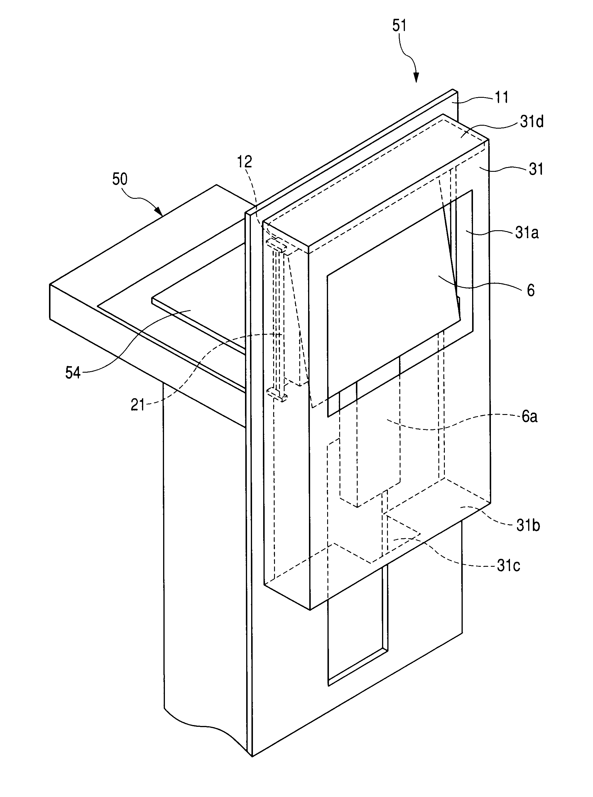
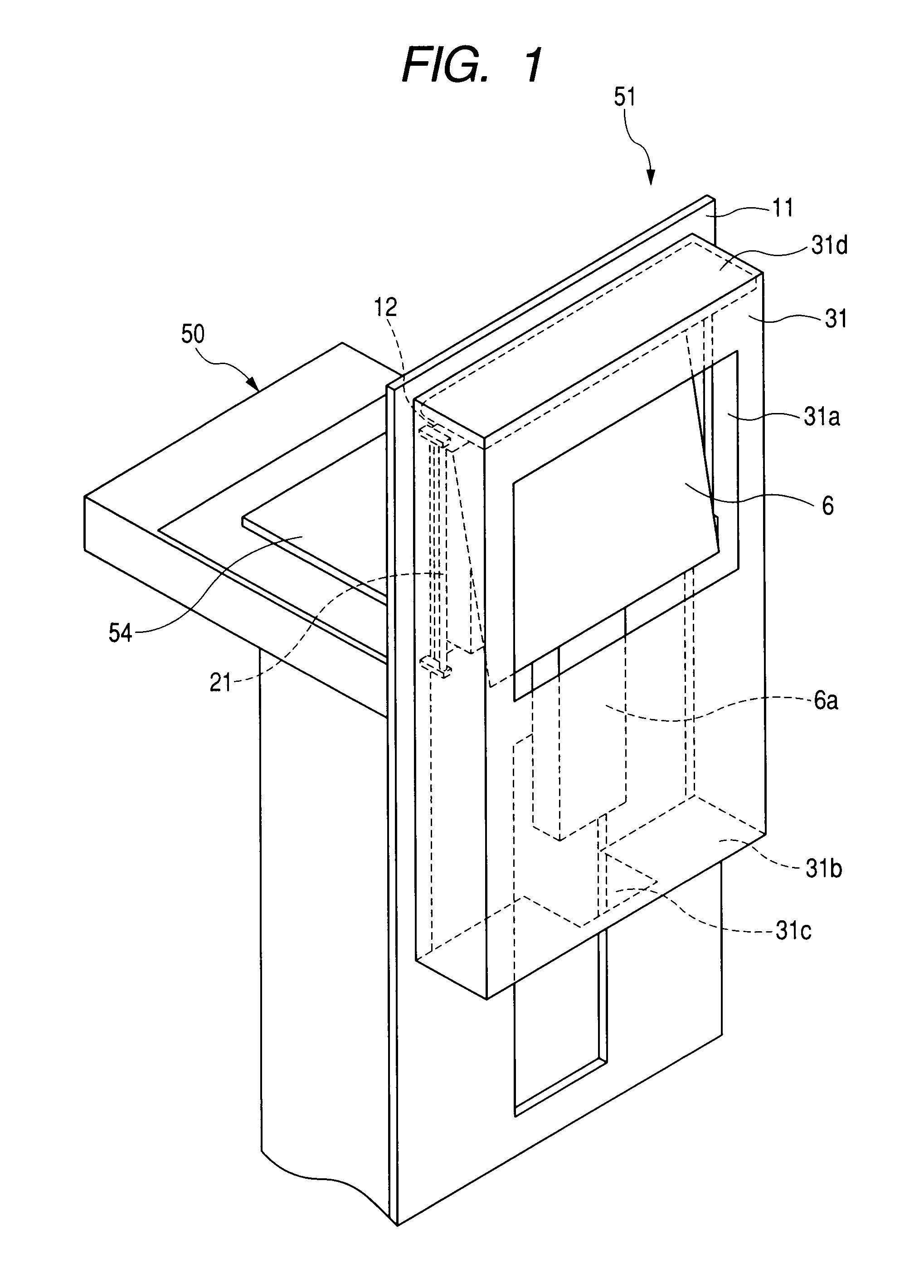
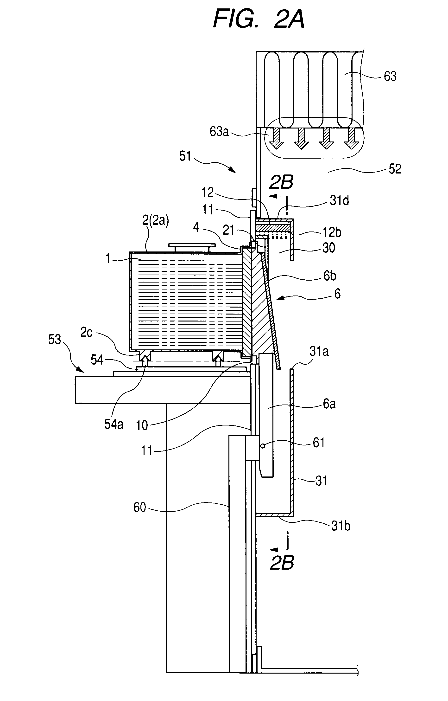
[0031]In the following, an embodiment of the present invention will be described with reference to the accompanying drawings. FIG. 1 is a schematic perspective view seen from the mini-environment side. FIG. 1 shows the general structure of the relevant portions of a lid opening and closing apparatus (FIMS, which will be hereinafter referred to as a load port) according to an embodiment of the present invention. In FIG. 1, only the aforementioned support table, a door, a first opening portion, a part of a door opening and closing mechanism, a wall on which the first opening portion is provided and that partly defines a mini-environment and a novel enclosure that is provided according to the present invention and structures associated to them are shown. FIG. 2A is schematic cross sectional view of the load port and the pod in the state in which the pod is placed on the load port (or the support table) and the lid of the pod is in contact with the door. FIG. 2B is a cross sectional vie...


PUM


Abstract

Adjacent to an opening portion 10 in an FISM system is provided an enclosure that encloses the operation space of a door and has a second opening portion 31 opposed to the opening portion 10. A curtain nozzle is provided above the upper edge of the opening portion 10 in the upper portion in the enclosure. A purge gas is supplied from the curtain nozzle along a direction from the upper edge to the lower edge of the opening portion. In addition, a gas outlet through which the purge gas flows from the interior of the enclosure out into the exterior is provided on the wall of the enclosure to which the purge gas flowing in the above described direction is directed, whereby an increase in the partial pressure of oxidizing gases in the interior of the FOUP is prevented.

Description

BACKGROUND OF THE INVENTION[0001]1. Field of the Invention[0002]The present invention relates to what is called a FIMS (Front-opening Interface Mechanical Standard) system that is used in a semiconductor manufacturing process or the like to transfer wafers stored in the interior of a transfer container called a pod from one semiconductor processing apparatus to another. More specifically, the present invention relates to a FIMS system or a lid opening and closing system in which a closed container for storing wafers in the form of a pod called FOUP (Front-Opening Unified Pod) is placed thereon, the lid of the pod is opened and closed to bring wafers into it, and a purge mechanism that cleans the interior of the pod is provided.[0003]2. Related Background Art[0004]In the past, the semiconductor manufacturing process had been performed in what is called a clean room that is constructed by establishing a high degree of cleanliness in the room in which semiconductor wafers are handled. ...

Claims


Application Information

Patent Timeline
Patent Type & Authority Applications(United States)
IPC IPC(8): H01L21/67
CPCH01L21/67772Y10S414/135
Inventor OKABE, TSUTOMUEMOTO, JUN
Owner TDK CORPARATION
Why Eureka
Try Eureka