Solar energy charging/discharging system and charging/discharging method thereof

Inactive Publication Date: 2009-02-12
NATIONAL TSING HUA UNIVERSITY
View PDF4 Cites 22 Cited by
  • Summary
  • Abstract
  • Description
  • Claims
  • Application Information

AI Technical Summary

Benefits of technology

[0017]Compared to the prior art, the solar energy charging/discharging system of the invention provides the electric energy to a super-capacitor with lower impedance under lower sunlight density. Due to low impedance of the super-capacitor, the solar cell can be operated at a voltage approximating to the maximum operating voltage. Therefore, no matter under hi

Problems solved by technology

However, the solar cell can be only operated at a low operating voltage P2 under low sunlight density, such that it significantly

Method used


Image

  • Solar energy charging/discharging system and charging/discharging method thereof
  • Solar energy charging/discharging system and charging/discharging method thereof
  • Solar energy charging/discharging system and charging/discharging method thereof

Examples


Embodiment Construction

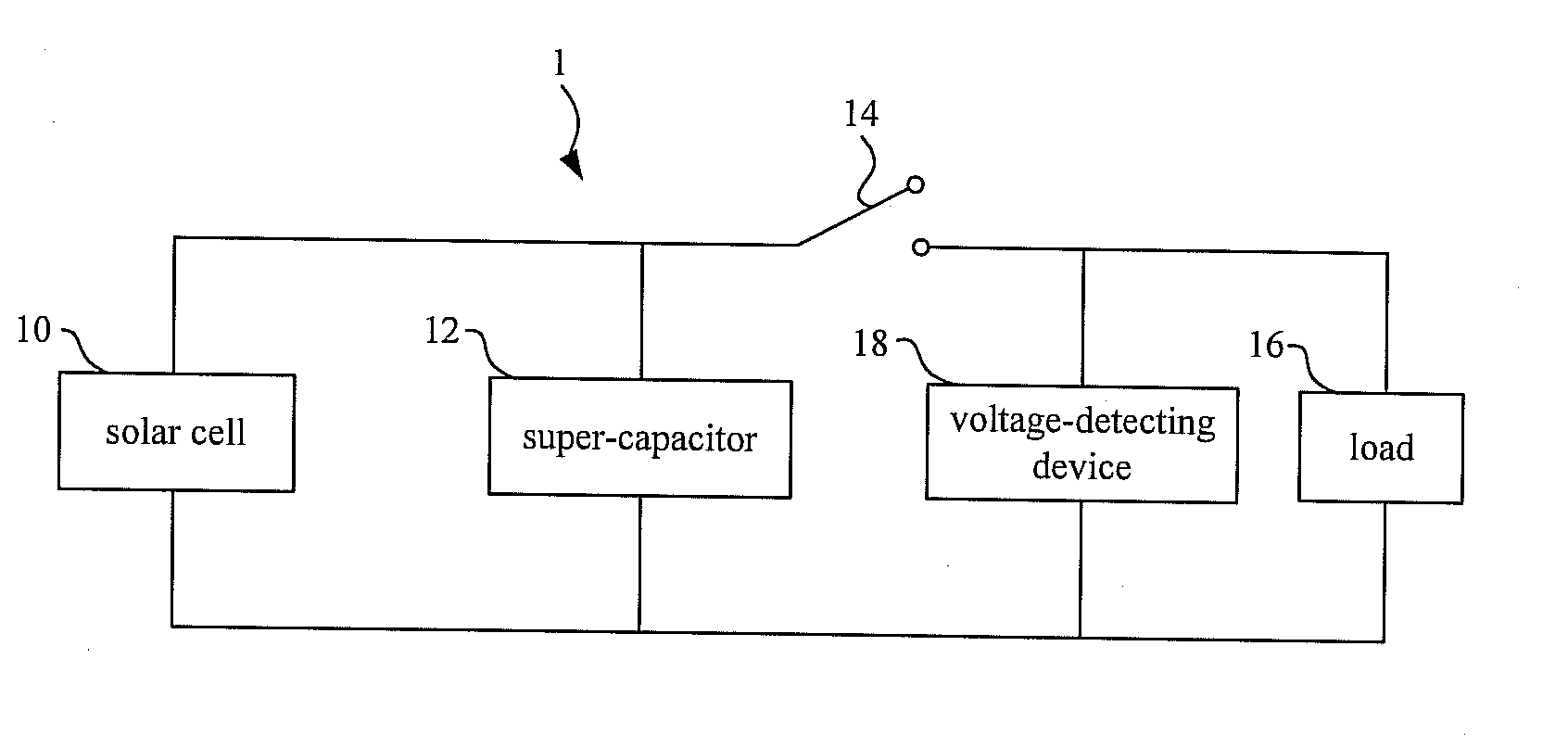
[0028]Please refer to FIG. 3A. FIG. 3A is a schematic diagram illustrating a solar energy charging / discharging system 1 according to an embodiment of the invention.

[0029]As shown in FIG. 3A, the solar energy charging / discharging system 1 comprises a solar cell 10, a super-capacitor 12, and a switch 14.

[0030]The super-capacitor 12 is an energy storage with high power capacity, high energy density. The super-capacitor 12 has the following advantages: 1) the capacitance unit is at Farad (F) scale, which is one million times a capacitance of a regular capacitor; 2) the charging / discharging rate is faster than a battery; 3) the charging / discharging times can reach one hundred thousand times, but a conventional rechargeable battery just can be charged or discharged with 300 to 2000 times; and 4) the load is extremely low.

[0031]The solar cell 10 is used for collecting a solar energy and converting the solar energy into an electric energy. The super-capacitor 12 is coupled to the solar cell...


PUM


Abstract

The invention discloses a solar energy charging/discharging system and a charging/discharging method thereof. The solar energy charging/discharging system according to the invention comprises a solar cell, a super-capacitor, and a switch. The solar cell is used for collecting solar energy and converting the solar energy into electrical energy. The super-capacitor is coupled to the solar cell. The super-capacitor and the solar cell are coupled to a load through the switch. The super-capacitor is selectively charged/discharged according to a threshold voltage.

Description

BACKGROUND OF THE INVENTION[0001]1. Field of the Invention[0002]The invention relates to a solar energy charging / discharging system and a charging / discharging method based on a solar cell.[0003]2. Description of the Prior Art[0004]A solar cell can convert light energy from a light source (e.g. sunlight) into electrical energy for equipment (e.g. calculator, computer, household appliances, etc.). In general, the solar cell is widespread in common usage.[0005]Please refer to FIG. 1. FIG. 1 is a characteristic curve diagram illustrating a relation between power and voltage under different sunlight degree. As shown in FIG. 1, a power generating performance under high sunlight density is properly better than a performance under low sunlight density. Besides, the curve 1 / ZL in FIG. 1 is a characteristic curve represents the reciprocal of a load impedance of the solar cell. The load can be a current converter, a storage (e.g. rechargeable battery), or a household appliances, etc.[0006]It s...

Claims


Application Information

Patent Timeline
IPC IPC(8): H02J7/00
CPCH02J7/345H02S40/38H02J7/35Y02E10/50
Inventor YEH, JER-LIANGLEE, JIA-YAN
Owner NATIONAL TSING HUA UNIVERSITY
Why Eureka
Try Eureka