Polishing apparatus, polishing method, substrate manufacturing method, and electronic apparatus manufacturing method

a technology of polishing apparatus and polishing method, which is applied in the direction of manufacturing tools, grinding machine components, lapping machines, etc., can solve the problems of reducing the degree of flatness, the edge of a chip or a generation of dust, etc., and achieves the effect of high polishing precision

Inactive Publication Date: 2009-02-12
FUJITSU LTD
View PDF12 Cites 25 Cited by
  • Summary
  • Abstract
  • Description
  • Claims
  • Application Information

AI Technical Summary

Benefits of technology

[0010]The present invention is directed to a polishing apparatus and polishing method that provide high polishing precision, and are configured to simultaneously polish both surfaces of the work.

Problems solved by technology

However, because the lower and upper stools rotate in opposite directions to one another, the work may oscillate in the accommodation part and collide with the carrier due to the frictional force and fitting, causing a chip of its edge or a generation of dust.
As a result, the work may get damaged with the dust entering a space between the pad surface and the polished surface of the work, and the degree of flatness lowers.

Method used


Image

  • Polishing apparatus, polishing method, substrate manufacturing method, and electronic apparatus manufacturing method
  • Polishing apparatus, polishing method, substrate manufacturing method, and electronic apparatus manufacturing method
  • Polishing apparatus, polishing method, substrate manufacturing method, and electronic apparatus manufacturing method

Examples


Embodiment Construction

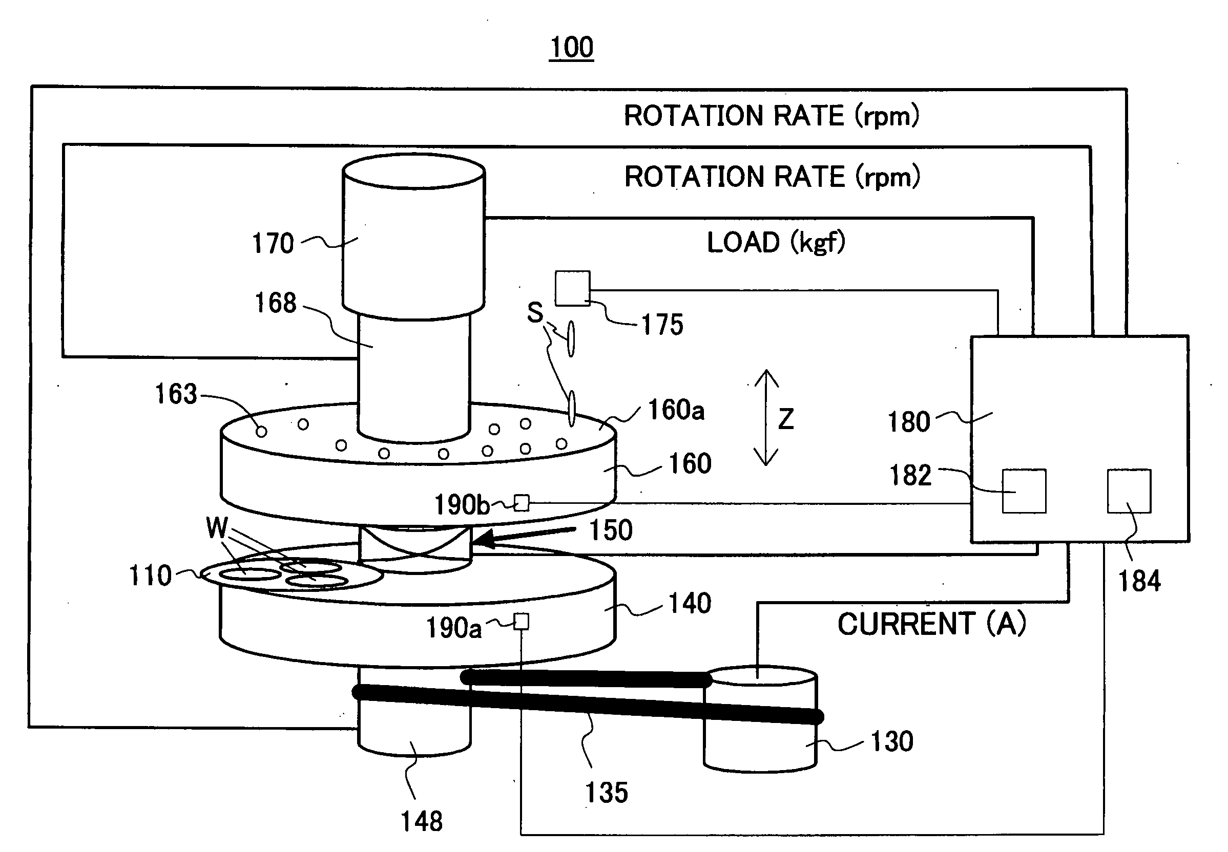
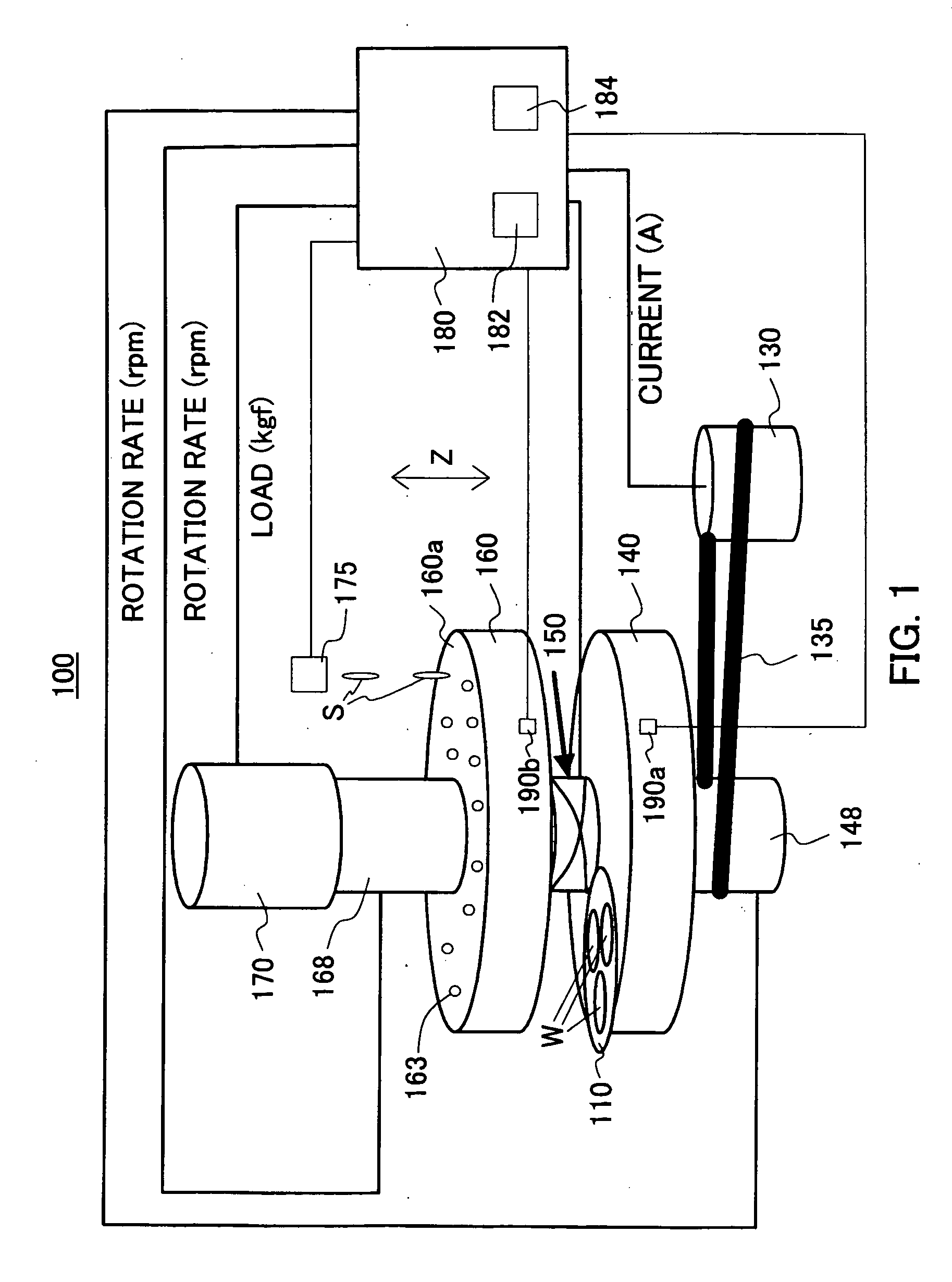
[0056]Referring now to the accompanying drawings, a description will be given of a polishing apparatus 100 according to one embodiment of the present invention. FIG. 1 is a schematic perspective view of a polishing apparatus 100. The polishing apparatus 100 is configured to chemically and mechanically polish both surfaces of a work W simultaneously, but the polishing apparatus of the present invention is applicable to any polishing apparatuses in addition to the CMP apparatus, such as a polishing apparatus for finishing.

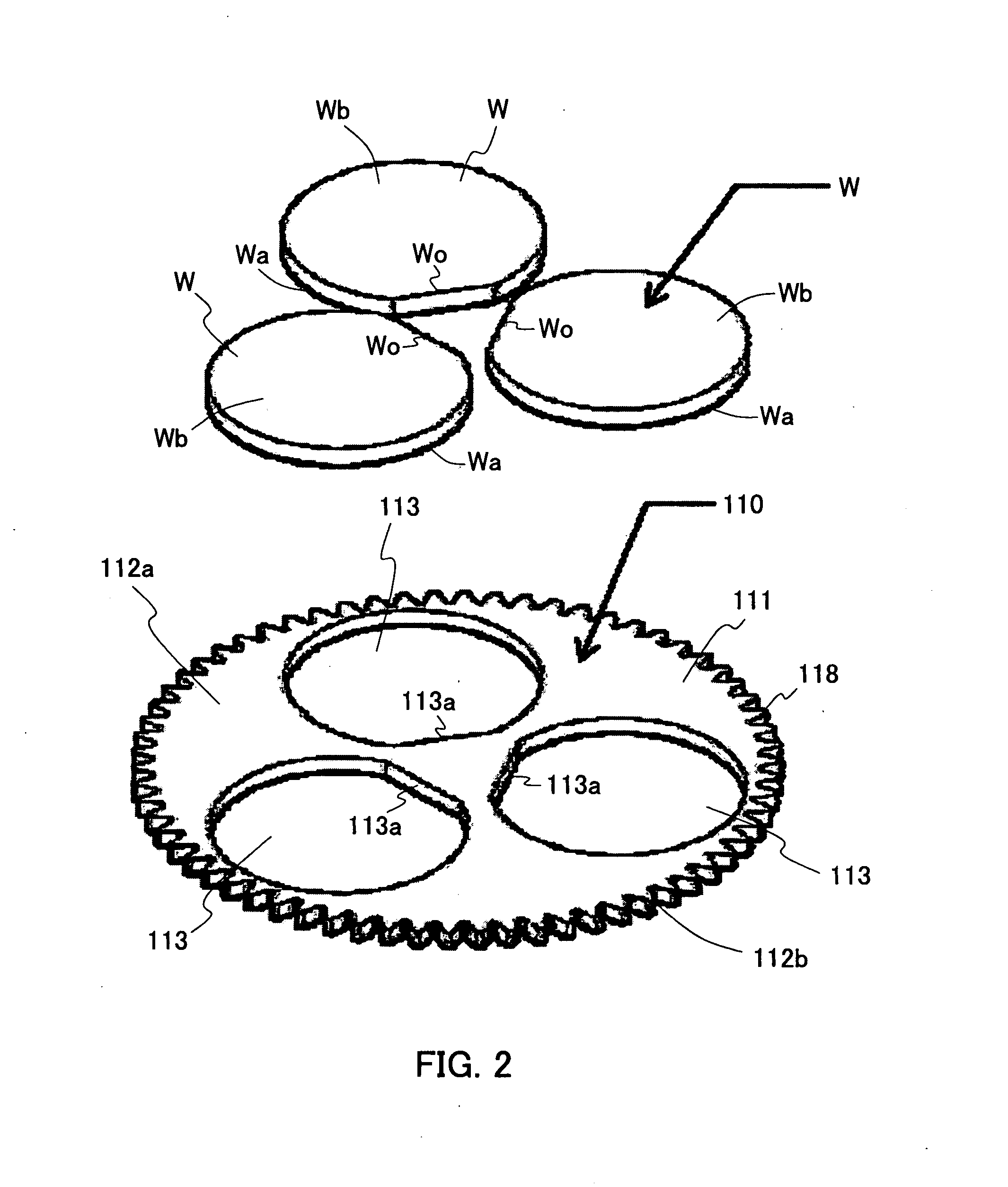
[0057]The work W of this embodiment is a substrate that is a target to be polished. The substrate includes a glass substrate, a silicon substrate, a ceramic substrate (including a laminate substrate), and any other substrates made of a single crystal material. A typical shape of those substrates is a disk shape (a disk shape with an orientation flat if the substrate is a wafer) or a rectangular plate shape. Usually, the substrate has a diameter or length of about doz...


PUM

PropertyMeasurementUnit
surface roughness Raaaaaaaaaaa
lengthaaaaaaaaaa
surface roughness RAaaaaaaaaaa

Abstract

A polishing apparatus is configured to simultaneously polish both surfaces of a work, and includes a pair of stools rotating in opposite directions, a pair of detecting units configured to detect rotation rates of the stools, a pressurizing unit configured to compress the work between the pair of the stools, a slurry supply unit configured to supply a slurry to the stool, and a control unit configured to reduce, when determining that a frictional force between the polishing surface and the work exceeds a threshold, at least one of a load applied by the pressurizing unit, the rotation rate of the stool, and a supply amount of the slurry supplied by the slurry supply unit.

Description

[0001]This application claims a foreign priority benefit based on Japanese Patent Application 2007-208396, filed on Aug. 9, 2007, which is hereby incorporated by reference herein in its entirety as if fully set forth herein.BACKGROUND OF THE INVENTION[0002]1. Field of the Invention[0003]The present invention relates generally to a polishing apparatus and a polishing method, and more particularly to a polishing apparatus and polishing method configured to polish both surfaces of a work. For example the present invention may be applied to a Chemical Mechanical Polishing or Planarization (“CMP”) polishing apparatus.[0004]2. Description of the Related Art[0005]A Micro Electro Mechanical System (“MEMS”) sensor is one example of MEMS and needs to be maintained in a vacuum environment by bonding a glass substrate to both sides of a MEMS chip having a sensing function. Accordingly, the MEMS chip side of the glass substrate needs to have a high degree of flatness. The manufacture becomes mor...

Claims


Application Information

Patent Timeline
Patent Type & Authority Applications(United States)
IPC IPC(8): B24B7/26B24B7/24B24B7/22B24B49/00B24B49/10B24B49/16B81C99/00
CPCB24B49/16B24B37/08H01L21/304
Inventor TOKURA, FUMIHIKOTAKEUCHI, MITSUO
Owner FUJITSU LTD
Why Eureka
Try Eureka