Sensor system with surface-plasmon-polariton (SPP) enhanced selective fluorescence excitation and method

a technology of surface plasmon polariton and fluorescence excitation, which is applied in the field of fluorescence detection, can solve the problems of difficult and inflexible detection geometry, and difficult to use in conventional fluorescence detection

Inactive Publication Date: 2009-02-19
MARYLAND UNIV OF
View PDF20 Cites 38 Cited by
  • Summary
  • Abstract
  • Description
  • Claims
  • Application Information

AI Technical Summary

Benefits of technology

[0010]It is therefore an object of the present invention to provide a sensor system with Surface-Plasmon-Polariton enhanced selected fluorescence excitation which is compatible with the geometry of current commercial Fluorescent Optical Microscopes (FOM) by allowing the illumination and detection from the front (air) side of the sample.
[0011]It is a further object of the present invention to provide a sensor system based on Surface-Plasmon-Polariton enhanced selected fluorescence excitation in which the behavior of the surface plasmon polaritons is controlled in an elegant and efficient fashion to obtain a strong fluorescent response.
[0012]It is another object of the present invention to provide a sensor system fully applicable in genomic, proteomic, chemical and biological applications which permits a sufficiently precise determination of presence of fluorescent genes, cells, DNA oligonucleotides, c-DNA, RNA, antibodies, antigens, proteins, etc., referred to herein further as fluorescent target molecules (particles) in specimens under study.
[0014]It is an additional object of the present invention to provide an active sensor chip with specimens applied to a plurality of dielectric periodically nano-patterned sensor patches of different periodicities, and alternatively of distinct geometries, which are interrogated by illuminating the patches in a predetermined sequential order. During the interrogation, the wavelength of the illumination, incidence angle, polarization directions, and azimuthal orientation of the light beam are controlled depending on the periodicity of the respective periodically patterned patch to provide optimal conditions for generation of the fluorescence signal emanating from each patch for precise detection of particulates of interest in each specimen.
[0022]Different fluorescence dyes, including different surface tags, may be used for different patches in a multi-patch sensor chip arrangement. The surface tags bind specifically to fluorescent target particles of interest. The corrugated surface may help to capture more test material thus increasing the concentration of fluorophore labels (fluorescently labeled target particles of interest) on the surface. The periodically patterned surface holds binding agents and / or fluorophores in close proximity to the metal film, which is substantially the place where fluorescence by SPPs is efficiently excited. The trajectories of the SPPs are modified by the periodically shaped nano-structures to produce excitation “hot spots” determining the patterns of excitation. By controlling the behavior of the SPPs, e.g., the trajectories of their propagation, by varying the wavelength, incident angles, polarization direction, azimuthal orientation of the excitation light beam, the fluorescence patterns from surface bound fluorophores (fluorescently labeled target particle of interest) may be controlled to strengthen the fluorescent signal and to discriminate against fluorescence from non-bound fluorophores in a specimen above the surface of the patch.
[0029]controlling the surface plasmon polariton behavior to enhance the fluorescent response and to obtain a desired fluorescent pattern distinct for each target particle of interest.

Problems solved by technology

The drawback of Lakowicz, et al's system is that the fluorescence emerges as a cone of light on the backside of the optical arrangement making the detection geometry difficult and inflexible.
The total internal reflection geometry used by Lakowicz, et al. and in various prior art sensors, makes them difficult to use in conventional fluorescence detection since the fluorescence does not emerge from the air (front) side of the device and further requires complex optics.

Method used


Image

  • Sensor system with surface-plasmon-polariton (SPP) enhanced selective fluorescence excitation and method
  • Sensor system with surface-plasmon-polariton (SPP) enhanced selective fluorescence excitation and method
  • Sensor system with surface-plasmon-polariton (SPP) enhanced selective fluorescence excitation and method

Examples


Embodiment Construction

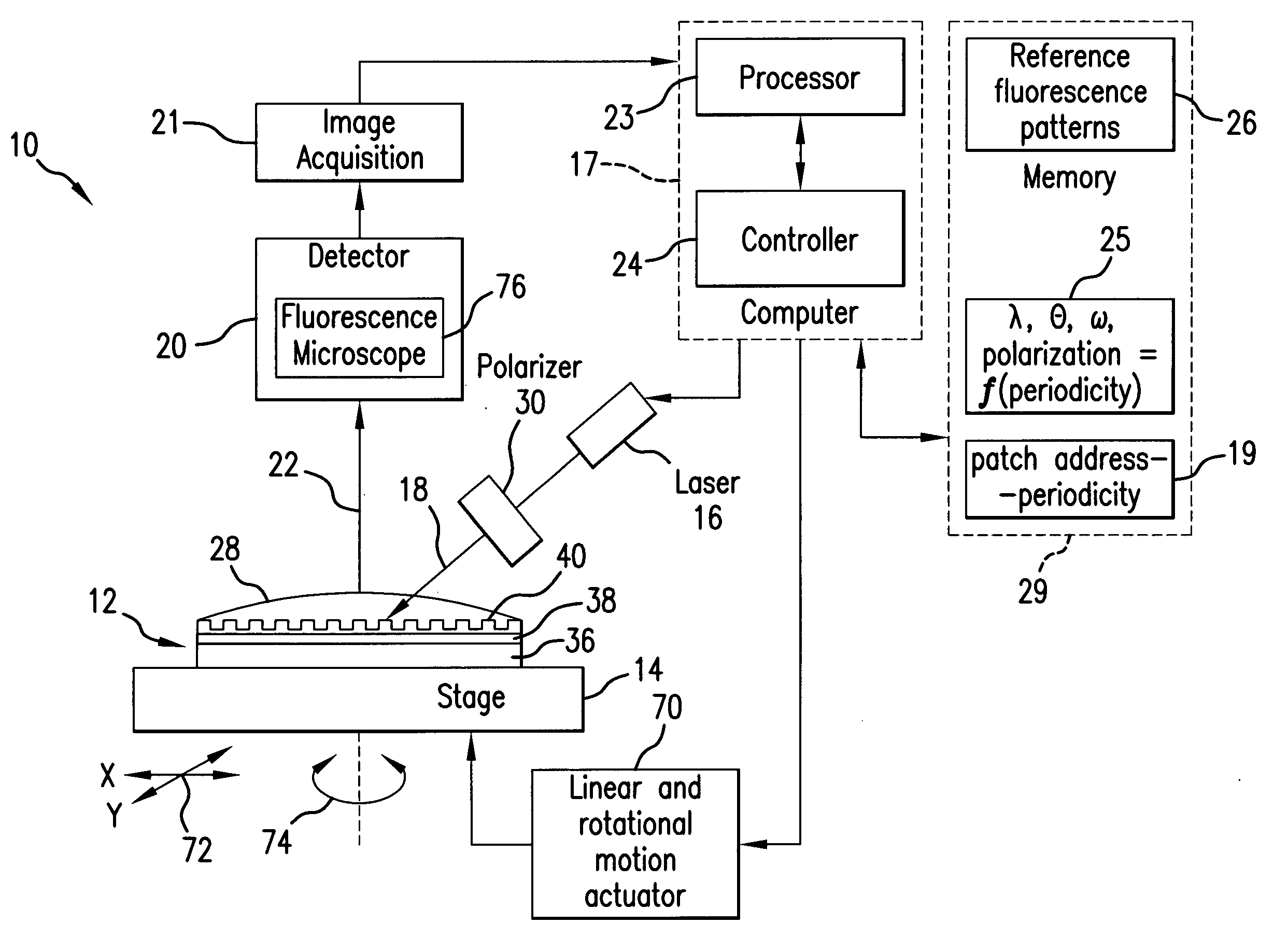
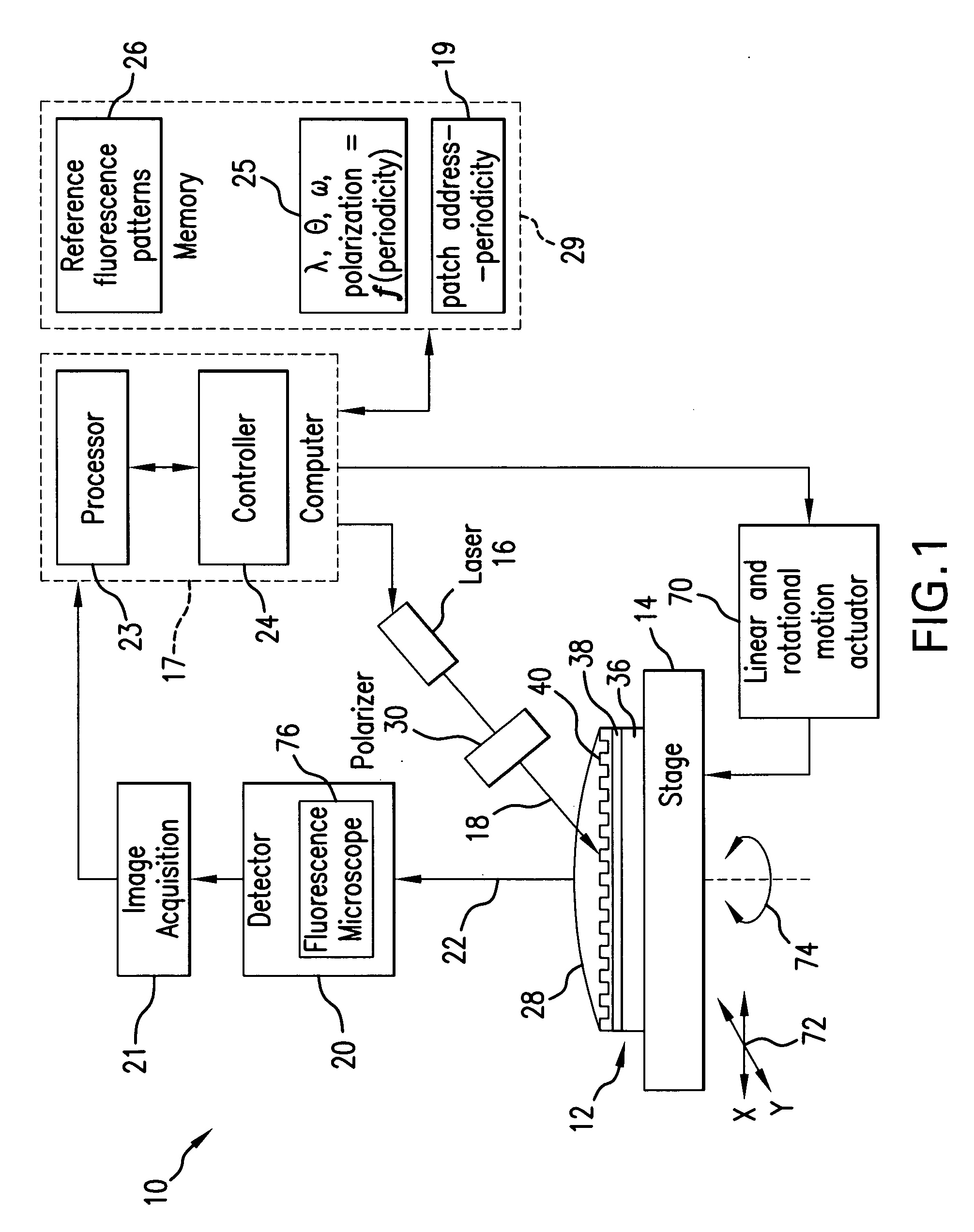
[0052]Referring to FIG. 1, a sensor system 10 of the present invention includes an active sensor chip 12 positioned on a stage 14 and secured thereto, a source of excitation light 16 for generating an excitation light beam 18, a computer 17, a detector unit 20 for detecting a fluorescence signal 22, an image acquisition unit 21, a processor unit 23 for processing the detected fluorescence signal and controlling the parameters of sensor system 10, as will be further described in detail. The system 10 further includes a controller unit 24 actuated by the processor unit 23 to apply the control parameters to the excitation source 16 and to the stage 14, as will be presented in detail further herein.

[0053]The computer 17 communicates with a database 25 which contains controlling parameters and relationships therebetween to apply the latter to the system 10 during interrogation of the active sensor chip 12, as will be described in further paragraphs. The computer 17, specifically the proc...


PUM


Abstract

In a sensor system, an active sensor chip includes an array of periodically-patterned dielectric active sensor patches of different periodicities and geometries formed on a metal film. A specimen under study is positioned on each patch, and the active sensor chip is interrogated by illumination the patches in a predetermined sequence to result in a fluorescence response from each patch enhanced by SPP. The intensity of the fluorescence response is controlled by varying the wavelength, incidence angle, azimuthal orientation and polarization direction of the excitation light beam as the function of the periodicity of the illuminated patch. The system is compatible with commercial fluorescence microscopes and scanned laser interrogation systems.

Description

STATEMENT REGARDING FEDERALLY SPONSORED RESEARCH[0001]The invention described herein was developed through research sponsored by the NSF, Contract Nos. ECS0304046 and ECE0508275. The United States Government has certain rights to the invention.RELATED APPLICATION DATA[0002]This Utility patent application is based on Provisional Patent Application Ser. No. 60 / 885,996 filed on 22 Jan. 2007.FIELD OF THE INVENTION[0003]The invention described herein is related to fluorescence detection, and particularly, to a Surface-Plasmon-Polariton (SPP) enhanced fluorescence sensor.[0004]More in particular, the present invention is directed to a sensor system based on Surface-Plasmon-Polariton assisted fluorescence excitation attained by forming a periodically patterned dielectric nano-structured surface on a metal film which facilitates controlling the behavior of the surface plasmon polaritons existing in the vicinity of the boundary between the metal and the dielectric to obtain an enhanced fluor...

Claims


Application Information

Patent Timeline
Patent Type & Authority Applications(United States)
IPC IPC(8): G01J1/58
CPCG01N21/6458G01N2021/6432G01N21/648
Inventor SMOLYANINOV, IGOR I.HUNG, YU-JUDAVIS, CHRISTOPHER C.
Owner MARYLAND UNIV OF
Why Eureka
Try Eureka