Bonded slit valve door seal with thin non-metallic film gap control bumper

a technology of non-metallic film and slit valve, which is applied in the direction of slide valve, valve arrangement, mechanical equipment, etc., can solve the problems of metal-to-metal contact, contamination of wafer processing, and still may occur, so as to prolong the life of the seal

Active Publication Date: 2009-02-19
PARKER INTANGIBLES LLC
View PDF16 Cites 30 Cited by
  • Summary
  • Abstract
  • Description
  • Claims
  • Application Information

AI Technical Summary

Benefits of technology

[0012]The present invention provides a thin film spacer for maintaining a gap between a slit valve door and a sealing surface of a slit valve, such as a metallic insert. The film spacer can extend the life of a seal by limiting the line of sight exposure of the seal to corrosive gases within a wafer processing chamber, for example, and by controlling the compression percentage of the seal. The spacer may be located on an outer ambient side of the slit valve away from any corrosive gasses that may exist in the chamber.
[0013]Accordingly, a slit valve door or slit valve comprises a sealing face and a thin film spacer on the sealing face for maintaining a minimum gap between the sealing face and a corresponding sealing surface. A seal element on the sealing face can be provided for sealing against the corresponding sealing surface. The spacer can be located outwardly from the seal element on an ambient side thereof such that the spacer will not be exposed to corrosive gasses in the chamber and, therefore, is not generally subject to accelerated degradation by the same. By maintaining a minimum gap between the door and the slit valve, the spacer provides for consistent compression of the seal and, therefore, also can prevent overcompression of the seal and potential premature wear. The reduced minimum gap between the door and chamber achieved with the spacer results in decreased line of sight exposure of the seal to corrosive gasses in the chamber and, thus, seal life can be extended.
[0015]In accordance with another aspect, a slit valve assembly comprises a slit valve having a valve opening and a sealing surface surrounding the valve opening, and a slit valve door movable between open and closed positions to respectively permit and block flow through the valve opening of the slit valve. The slit valve door has a sealing face for sealing against the sealing surface of the slit valve. A thin film spacer is provided on at least one of the sealing face of the slit valve door and the sealing surface of the slit valve for maintaining a minimum gap between the sealing face and the sealing surface when the door is in a closed position.
[0017]In accordance with another aspect, a slit valve door comprises a multi-plane sealing face, and a seal element received in a groove in the sealing face for sealing against an opposed multi-plane sealing face of a slit valve. The sealing element has a portion thereof that protrudes from the groove beyond the surface of the sealing face to form a seal bead. The seal element can also include a second portion thereof that protrudes from the groove beyond the sealing face of the slit valve door, the second portion being spaced apart from the seal bead and configured to limit line-of sight exposure of the seal bead to corrosive gasses when the door is installed in a slit valve assembly and in a closed position. The seal element can be generally surrounded on three sides by the valve door. A thin film spacer can be provided for maintaining a minimum gap between the slit valve door and a corresponding sealing surface of a slit valve.

Problems solved by technology

The metal-to-metal contact between a slit valve door and the metal insert may provide a very good seal, but metal-to-metal contact may create microscopic particles that scrape off of the metal and get into the otherwise relatively clean environment of the vacuum chambers.
Such particles may land on the wafers in the chambers, thereby contaminating them.
Such contamination is undesirable in the processing of wafers.
However, since the seal between the O-ring and the slit valve is not static, but rather is constantly being opened and closed such that there is rubbing and abrading on the O-ring from the slit valve insert, some particle generation, typically from the 0-ring, still may occur.
Typically, controlling the gap size has involved tedious adjustment of the door and / or calibration of the actuator.
Fatiguing of the o-ring or vulcanized seal through dynamic cycling of the slit valve door can result in plastic deformation of the elastomer which leads to inconsistent gapping between the slit valve door and the slit valve (and / or insert).
Inconsistent gapping can result in seal over-compression, metal-to-metal contact between the slit valve door and the slit valve, high exposure levels of the sealing element to corrosive process gases, and premature degradation of the seal.

Method used


Image

  • Bonded slit valve door seal with thin non-metallic film gap control bumper
  • Bonded slit valve door seal with thin non-metallic film gap control bumper
  • Bonded slit valve door seal with thin non-metallic film gap control bumper

Examples


Embodiment Construction

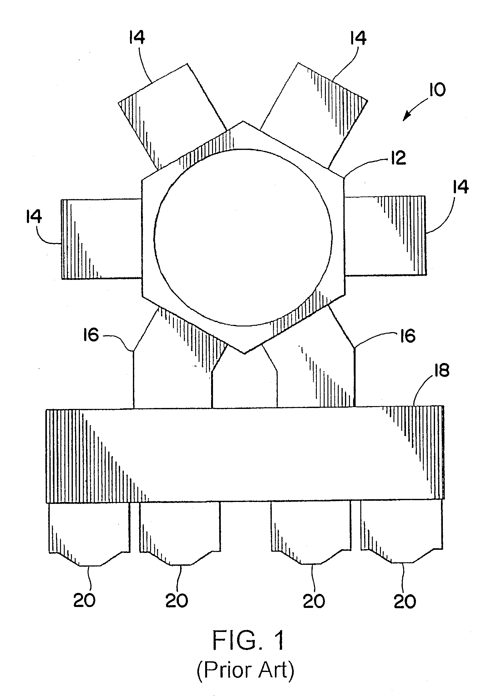
[0032]Referring now in detail to the drawings and initially to FIG. 1, an exemplary prior art vacuum processing system is generally indicated at 10. The system 10 comprises a series of vacuum chambers 14 attached to a central vacuum transfer chamber 12. A pair of vacuum load lock chambers 16 provide a passageway to a mini-environment 18. Pod loaders 20 are shown attached to the mini-environment 18. This system is an example of a cluster tool.

[0033]The vacuum chambers 14 may be connected to the transfer chamber 12 at an airtight seal which permits wafers to pass between the chambers 12, 14 and 16 without losing the vacuum in the chambers. The pod loaders 20 are attached to the mini-environment 18 and may be loaded with wafer cassettes (wafer holders) by a person or by an automated machine that is part of the over-all automated manufacturing system of the manufacturing plant or building that houses the vacuum processing system 10. A robot (not shown) within the mini-environment 18 may...


PUM


Abstract

The present invention provides a thin film spacer for maintaining a gap between a slit valve door and a sealing surface of a slit valve, such as a metallic insert. The film spacer can extend the life of a seal by limiting the line of sight exposure of the seal to corrosive gases within a wafer processing chamber, for example, and by controlling the compression percentage of the seal. The spacer may be located on an outer ambient side of the slit valve away from any corrosive gasses that may exist in the chamber.

Description

RELATED APPLICATIONS[0001]This application claims the benefit of U.S. Provisional Application Nos. 60 / 955,891 filed Aug. 15, 2007, and 60 / 955,672 filed Aug. 14, 2007, and 61 / 029,436 filed Feb. 18, 2008, all of which are hereby incorporated herein by reference.FIELD OF THE INVENTION[0002]The present invention relates generally to seal assemblies for valves and more particularly to slit valve door seal assemblies having particular use in forming a seal between chambers in vacuum equipment employed in the semiconductor industry for chip manufacture.BACKGROUND OF THE INVENTION[0003]Vacuum systems for manufacturing integrated circuits on wafers are generally known. A vacuum processing system may typically have a centralized vacuum chamber, called a transfer chamber, which may be part of a mainframe, for transferring wafers from one process chamber or load lock chamber to the next. A vacuum processing system may also typically have some kind of subsystem, such as a mini-environment, for p...

Claims


Application Information

Patent Timeline
Patent Type & Authority Applications(United States)
IPC IPC(8): F16K3/00
CPCF16K3/0227F16K51/02F16K3/16
Inventor KAMIBAYASHIYAMA, JULIAN
Owner PARKER INTANGIBLES LLC
Why Eureka
Try Eureka