Position detection apparatus

a detection apparatus and position technology, applied in the field of position detection apparatus, can solve the problems of inability to perform the position detection with the same high precision that is required by the lens position detection apparatus for camera zooming or auto focusing, and the instability of a magnetic characteristic may be increased, so as to reduce the effect of detection precision, simple circuit configuration, and high precision

Active Publication Date: 2009-02-19
ASAHI KASEI ELECTRONICS CO LTD
View PDF25 Cites 41 Cited by
  • Summary
  • Abstract
  • Description
  • Claims
  • Application Information

AI Technical Summary

Benefits of technology

[0054]According to the present invention, it is possible to suppress an effect on detection precision due to non-uniformity in a magnetic field of the magnetism sensing section. Even when constituent components such as magnet and magnetic flux detection means are constructed by using a general-purpose part, easily-available part or the like, miniaturization can be achieved with a simple circuit configuration. Furthermore, a position detection apparatus that detects a distance in a wide range of about 10 mm (such detection being not possible to perform according to the conventional art) with a high precision of 1% or less can be constructed.

Problems solved by technology

However, in the conventional art, position detection with a wide range of 10 mm that is required by the lens position detection apparatus for camera zooming or auto focusing cannot be performed with the same high precision.
Further, as a magnetic sensor, when position detection with a wide range is performed using such a method as described in Patent Document 3, since the magnet used is not a general-purpose one, it is difficult to fabricate the magnet.
In addition, since it is difficult to form a uniform magnet shape, the instability of a magnetic characteristic may be increased or the acquisition of such magnet may be difficult.
Also, in a configuration that position detection with a wide range is performed using a method described in a later-described comparative example (the technique described in Patent Document 1), when a design is made so that the differential value between Hall output voltages is varied linearly to the movement distance of the permanent magnet in a lateral direction, the magnet size, the distance between the two Hall sensors, and the distance between the Hall sensor and magnet become large and thus it is difficult to miniaturize the position detection apparatus.
Since miniaturization is strongly required in a mobile apparatus such as a digital still camera, the configuration is not practical.

Method used


Image

  • Position detection apparatus
  • Position detection apparatus
  • Position detection apparatus

Examples


first example

[0082]A first embodiment of the present invention will be described with reference to FIGS. 1 to 9.

[0083]A position detection apparatus according to the present invention can be constructed using various shapes of magnets and various types of Hall sensors.

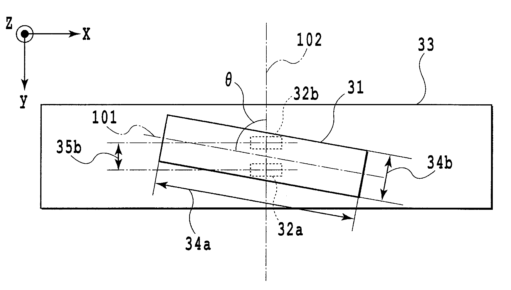
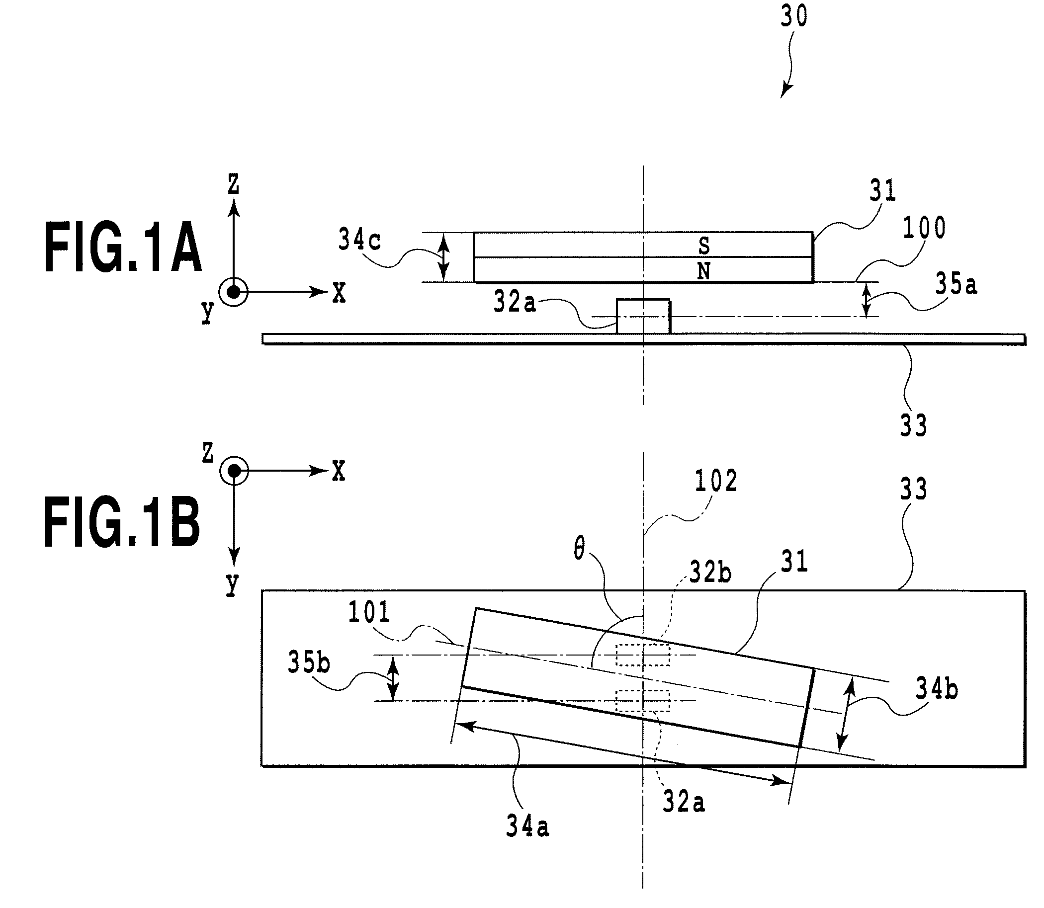
[0084]FIGS. 1A and 1B shows a schematic configuration of a position detection apparatus 30.

[0085]Reference numeral 31 denotes a rectangular solid magnet (a magnetic flux generation means) having one N-pole and one S-pole separately magnetized.

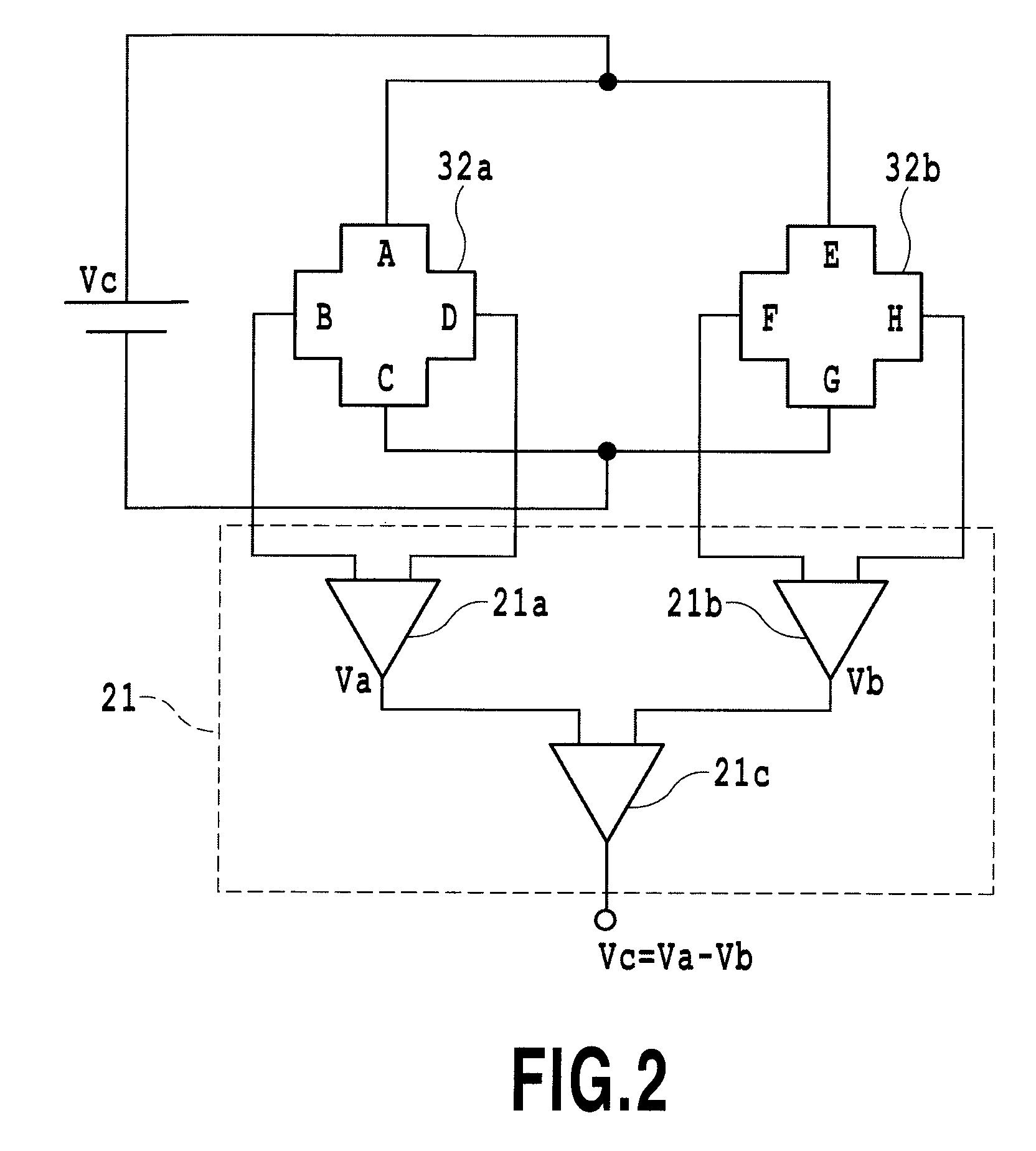
[0086]Reference numeral 32a and 32b denote each Hall Sensor composing a pair of two Hall sensors (magnetic flux detection means).

[0087]Reference numeral 33 denotes a substrate having the Hall sensor 32a (first Hall sensor) and the Hall sensor 32b (second Hall sensor).

[0088]The rectangular solid magnet 31 is magnetized in a direction orthogonal to the substrate 33 having the Hall sensors 32a and 32b.

[0089]The rectangular solid magnet 31 is arranged movably along an x-direction on a plane 100 f...

embodiment

[0111]An embodiment of the position detection apparatus 30 will be described.

[0112]A case where a position is detected within a range of 8 mm (±4 mm) at a resolution of 30 μm in a wide temperature range is described. An example of designing optimal values of parameters of each constituent component in FIG. 1 is described.

[0113]It is assumed that the length 34a of the rectangular solid magnet 31 in a long side direction X is 9.7 mm. The length 34b of the rectangular solid magnet 31 in a short side direction Y is 1.4 mm. The length 34c of the rectangular solid magnet 31 in a thickness direction Z (the length of the magnet in a magnetization direction) is 1.0 mm.

[0114]Also, it is assumed that the distance 35a from the plane 100 of the rectangular solid magnet 31 opposite to the Hall sensors 32a and 32b to the center of magnetism sensing section of the Hall sensors 32a and 32b is 0.5 mm. The distance 35b between the center of magnetism sensing section of the Hall sensor 32a and the cent...

second example

[0139]A second embodiment of the present invention will be described with reference to FIGS. 10 and 11. Here, the same reference characters are applied to parts corresponding to the above described first example, and an explanation thereof is omitted.

[0140]Multiple pairs of two Hall sensors may be combined in the position detection apparatus 30 of the above example of FIG. 1.

[0141]In this example, there will be described an exemplary specific configuration of a position detection apparatus that multiple pairs of Hall sensors are included and the size of magnet is reduced.

[0142]Similarly to the above described first example, a case where a position is detected with a range of 8 mm (+4 mm) at a resolution of 30 μm in a wide temperature range is described.

[0143]FIGS. 11A and 10B show an exemplary configuration of a position detection apparatus 50 using a magnet and Hall sensors according to the present invention.

[0144]Reference numeral 51 denotes a rectangular solid magnet magnetized i...


PUM


Abstract

A magnetic flux detection unit and a rectangular solid magnet are provided. The magnetic flux detection unit includes one or more pairs of Hall sensors, each pair having two Hall sensors arranged on a substrate. The solid magnet is arranged movably in a direction in a plane parallel to the substrate. Each pair of two Hall sensors is arranged on the substrate so that a line connecting the centers of magnetism sensing sections of each pair of two Hall sensors is orthogonal to a movement direction of the magnet. A tetragon has a long side and a short side and the long side has a inclination angle to the line connecting the centers of magnetism sensing sections of the each pair of two Hall sensors. The magnet has one N-pole and one S-pole separately magnetized in orthogonal to the substrate on which the Hall sensors are arranged.

Description

TECHNICAL FIELD[0001]The present invention relates to a position detection apparatus using a magnet and Hall sensors.BACKGROUND ART[0002]In recent years, various types of sensors have been used in all fields. For example, hand movement correction apparatuses used in a digital still camera, digital video camera or the like, or lens position detection apparatuses used for zooming or automatic focusing may need a sensor having a function of performing position detection instantaneously with high precision. At the same time, with recent increasing demands for miniaturization of the entire apparatus miniaturization of the sensor may be required in itself. Further, sensors having such characteristics as extension of life and being hard to be affected by dust, oil (grease) and the like may be required.[0003]In order to satisfy the above requirements, a position detection method using a magnetic sensor as the sensor is a well known technique.[0004]For example, as the magnetic sensor, a meth...

Claims


Application Information

Patent Timeline
Patent Type & Authority Applications(United States)
IPC IPC(8): G01B7/14
CPCG01D5/145G01B7/003G01R33/072G01V3/102
Inventor NISHIDA, SOSUKETAKATSUKA, TOSHINORI
Owner ASAHI KASEI ELECTRONICS CO LTD
Why Eureka
Try Eureka