Fuse cell and method for programming the same

a technology of fuse cell and programming method, which is applied in the field of fuses, can solve the problems of high programming voltage exposure of on-chip devices coupled to such fuse pads, damage to on-chip devices, and intact fuse structures, etc., and achieve the effect of reducing the yield loss of i

Active Publication Date: 2009-02-19
HONG KONG APPLIED SCI & TECH RES INST
View PDF9 Cites 40 Cited by
  • Summary
  • Abstract
  • Description
  • Claims
  • Application Information

AI Technical Summary

Benefits of technology

[0018]It is a primary object of this invention to overcome the shortcoming of known existing fuse structures and trimming methods and provide improved fu...

Problems solved by technology

However, the on-chip devices that are coupled to such fuse pads are also exposed to such a high programming voltage.
Consequently, it happens that some of the on-chip devices, especially active devices such as transistors, comparators or operational amplifiers, are damaged by the over-voltage stress.
Unfortunately, it leads to another problem that some fuse structures remain intact and the resulting integrated circuits are not correctly trimmed.
This is due to manufacturing process variation or device failure that results in un...

Method used


Image

  • Fuse cell and method for programming the same
  • Fuse cell and method for programming the same
  • Fuse cell and method for programming the same

Examples


Embodiment Construction

[0036]The present invention is described in detail herein in accordance with certain preferred embodiments thereof. To describe fully and clearly the details of the invention, certain descriptive names were given to the various components. It should be understood by those skilled in the art that these descriptive terms were given as a way of easily identifying the components in the description, and do not necessary limit the invention to the particular description.

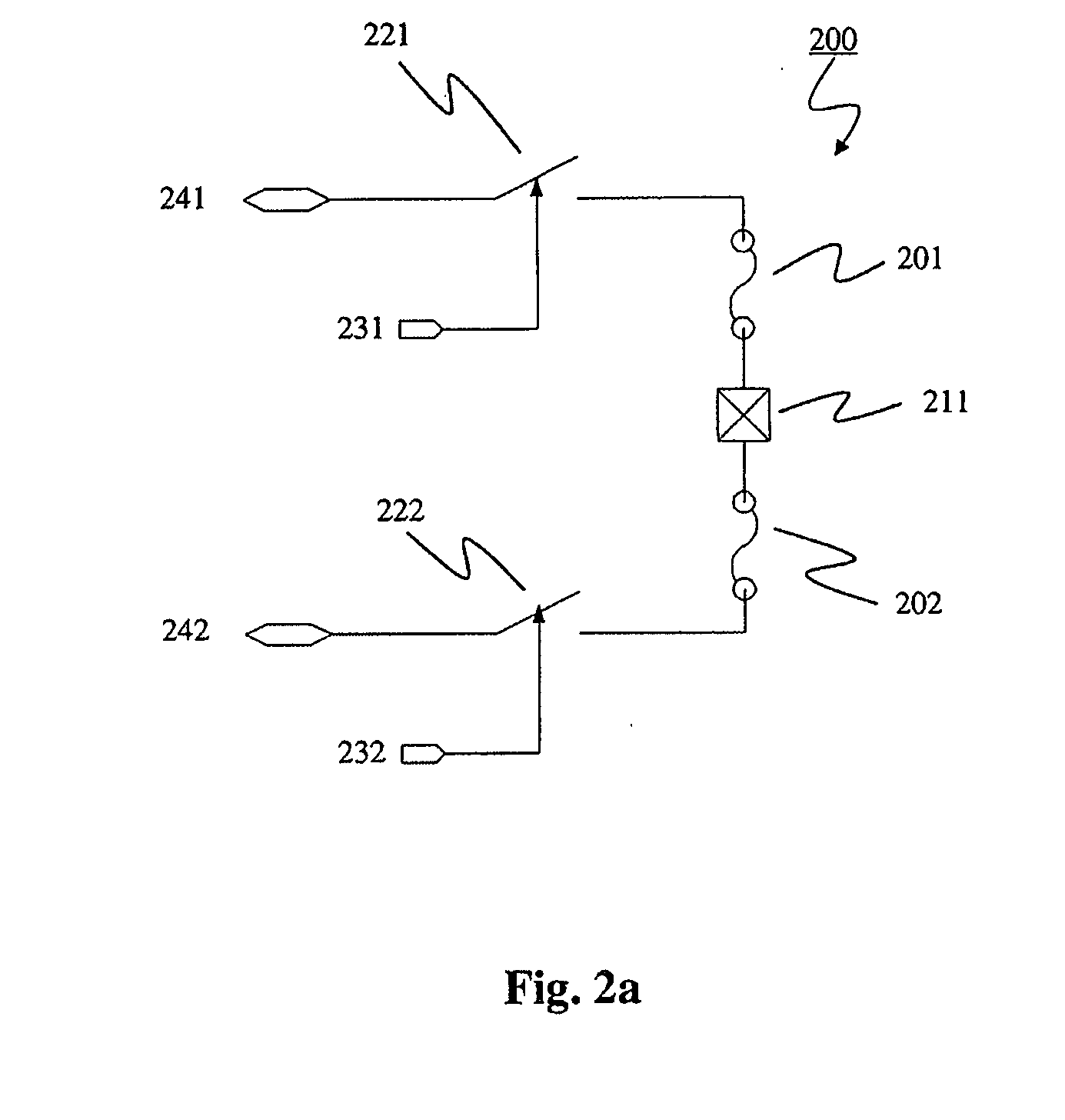
[0037]FIG. 2a shows a schematic diagram illustrating a fuse cell 200 according to an embodiment of the present invention. Instead of conventional configuration having a single fuse structure, the fuse cell 200 consists of two fuse structures 201, 202 connected in series. A programming node 211, usually in the form of a fuse pad, is disposed at the common end of the fuse structures 201, 202 for application of external programming voltage. Alternatively, the programming voltage is generated by on-chip circuit and the program...


PUM


Abstract

The fuse cell architecture 371 for the presently claimed invention employs a multiple fuse structure 301, 302 architecture in lieu of a single fuse structure. As such, the terminals of these fuse structures that couple to other on-chip devices are always at ground potential throughout the application of programming voltage to the fuse pads 311. This approach overcomes previous single fuse problems owing to the fact that a sufficiently high programming voltage can be applied to blow fuse structures with unexpectedly high resistance without damaging nearby on-chip devices. Furthermore, even if one of the fuse structures 301, 302 possessed an abnormally high resistance which would not be blown under typical conditions, the desired circuit trimming result can still be achieved owing to the blowing of the other fuse structure in the fuse cell 371.

Description

FIELD OF THE INVENTION [0001]The present invention relates generally to programmable passive components in integrated circuits (IC) and in particular to fuses.BACKGROUND [0002]In a number of applications for precision analog circuits, such as converters or precision voltage references, the absolute-value tolerances of circuit components such as resistance are important. However, it is difficult to guarantee absolute-value tolerances associated with semiconductor or thin-film resistors due to unpredictable variations in manufacturing process steps. Additional steps must be taken to trim the on-chip resistor network after its fabrication, to meet a given absolute-value tolerance. One common adjustment method is by the use of fusible links.[0003]A fuse can simply be a short section of minimum-width metal or polysilicon connected between two bond pads. It is programmed or blown, by passing a large current between the bond pads, causing the fuse material to vaporize. After programming, t...

Claims


Application Information

Patent Timeline
IPC IPC(8): H01H85/00
CPCG11C17/16Y02P80/30
Inventor KWONG, DAVID KWOK KUENWAN, HO MING KARENWAN, KAM CHUENNG, CHIK WAI
Owner HONG KONG APPLIED SCI & TECH RES INST
Why Eureka
Try Eureka