Distance measuring apparatus
a technology of distance measuring and measuring equipment, applied in the direction of digital signal error detection/correction, instruments, recording signal processing, etc., can solve the problems of affecting the measurement environment, affecting the measurement effect, and affecting the reflection intensity of the target object, so as to avoid the problem of dependence on wavelength and produce at a lower cost
- Summary
- Abstract
- Description
- Claims
- Application Information
AI Technical Summary
Benefits of technology
Problems solved by technology
Method used
Image
Examples
first embodiment
(1) First Embodiment
1-1: Structure of Laser Device
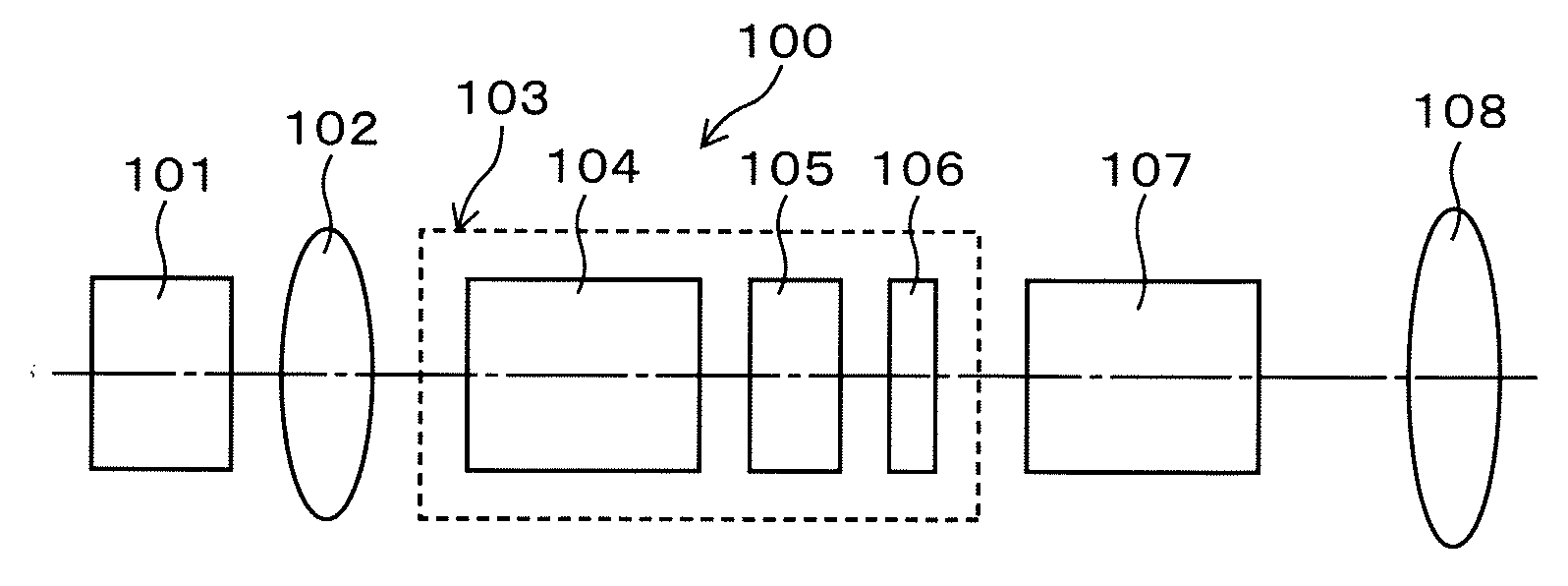
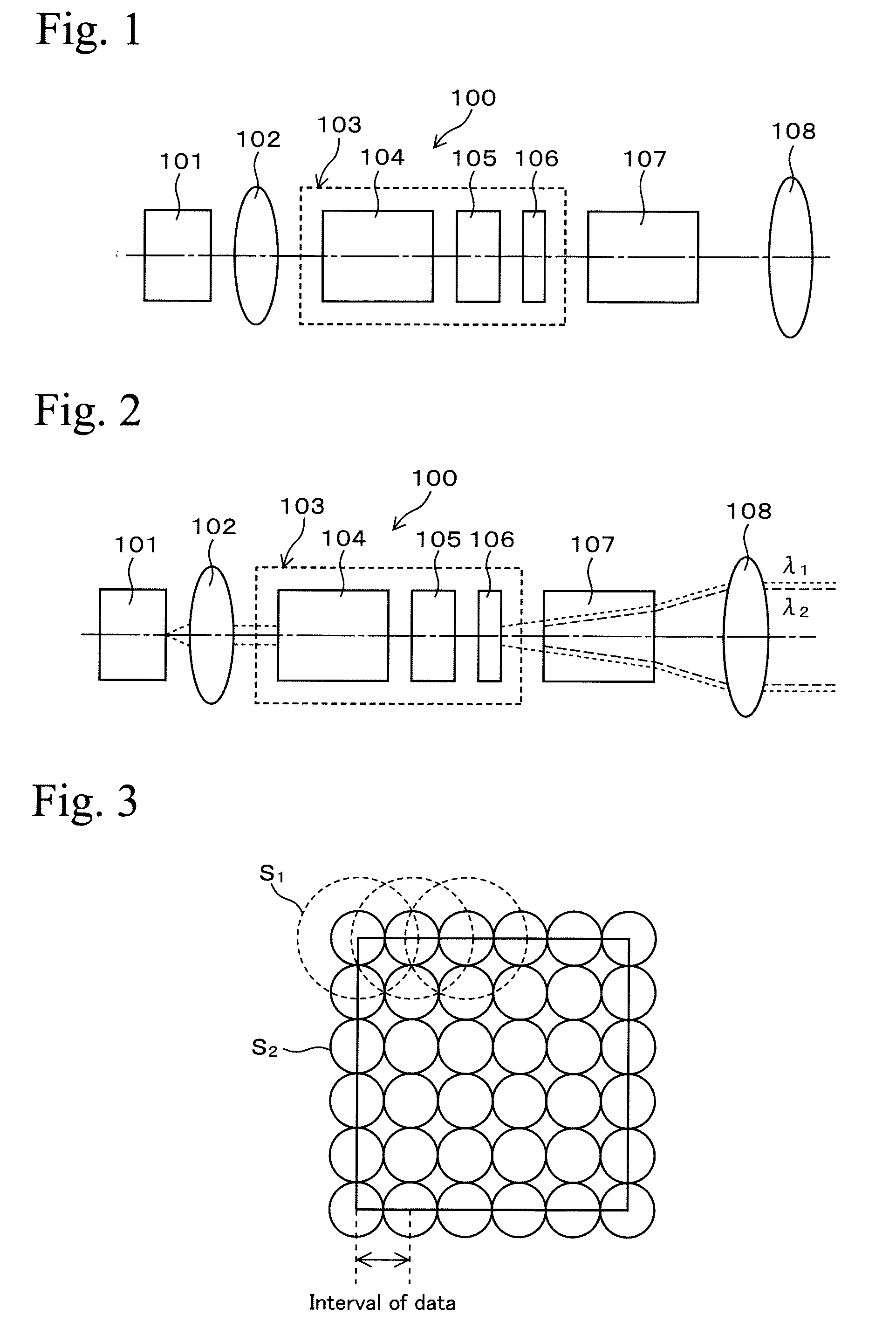
[0037]An example of a laser device for generating two kinds of laser beams having different wavelengths at the same time will be described. In this case, the laser device comprises a function of generating pulsed laser beams having different wavelengths. FIG. 1 is a schematic drawing showing an example of a laser device for generating two kinds of laser beams having different wavelengths at the same time. FIG. 1 shows a laser device 100 for generating a pulsed laser beam by Q-switching. The laser device 100 is an LD-pumped solid-state laser device (laser diode-pumped solid-state laser device) comprising a semiconductor laser unit 101, a focusing lens 102, a laser resonator 103, a nonlinear crystal 107, and a collimator lens 108.
[0038]The semiconductor laser unit 101 comprises an AlGaAs laser diode for generating a laser beam for excitation, which has an oscillation peak wavelength of 808 nm. The focusing lens 102 concentrates light o...
second embodiment
(2) Second Embodiment
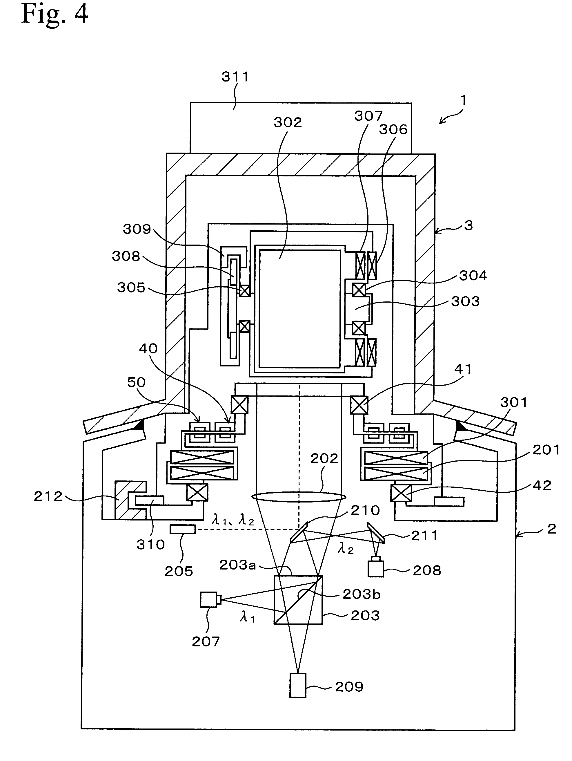
[0053]Hereinafter, an example of a distance measuring apparatus using a laser device that is exemplified in the First Embodiment will be described. FIG. 4 shows an example of a distance measuring apparatus using the present invention.
Outline of Distance Measuring Apparatus
[0054]FIG. 4 shows a distance measuring apparatus 1 comprising a body 2 and a rotational optical portion 3 that is rotatable with respect to the body 2. The rotational optical portion 3 is rotatably mounted on the body 2 via bearings 41 and 42. Data signal transmission between the body 2 and the rotational optical portion 3 and electric power supply from the body 2 to the rotational optical portion 3 are controlled via a data transmitting device 40 and an electric power transmitting device 50. These transmitting devices comprise coils at both sides of the body 2 and the rotational optical portion 3, and the coils at both sides have a rotational center as an axis and are slightly separated. Acco...
third embodiment
(3) Third Embodiment
[0099]In the laser device 100 shown in FIG. 1, a laser beam having a wavelength of 1064 nm enters into the nonlinear crystal 107 as a fundamental wave, and a laser beam having a wavelength of 532 nm is generated as a second harmonic wave. Then, two kinds of the laser beams having different wavelengths are output at the same time. The laser beam is not limited to having two kinds of wavelengths (1064 nm and 532 nm), and a nonlinear crystal for generating a third harmonic wave, a fourth harmonic wave, or a fifth harmonic wave may be appropriately used. The laser beam having a wavelength of 808 nm, which is excited by the semiconductor laser unit 101, may be changed. In this case, a preferable laser device is incorporated to the apparatus in view of a measuring distance, measurement environment, the color of a target object, safety for the eyes, a production cost, and the like.
PUM
| Property | Measurement | Unit |
|---|---|---|
| infrared wavelength | aaaaa | aaaaa |
| wavelength | aaaaa | aaaaa |
| oscillation peak wavelength | aaaaa | aaaaa |
Abstract
Description
Claims
Application Information
 - R&D
- Intellectual Property
- Life Sciences
- Materials
- Tech Scout
- Unparalleled Data Quality
- Higher Quality Content
- 60% Fewer Hallucinations
Browse by: Latest US Patents, China's latest patents, Technical Efficacy Thesaurus, Application Domain, Technology Topic, Popular Technical Reports.
© 2025 PatSnap. All rights reserved.Legal|Privacy policy|Modern Slavery Act Transparency Statement|Sitemap|About US| Contact US: help@patsnap.com


