
Medical imaging system

Inactive Publication Date: 2009-02-26
KONICA MINOLTA MEDICAL & GRAPHICS INC
View PDF4 Cites 49 Cited by
  • Summary
  • Abstract
  • Description
  • Claims
  • Application Information

AI Technical Summary

Benefits of technology

[0058]The invention of the present patent application provides a method for efficiently associating the image data generated by an image generating apparatus with patient information while a doctor is examining a patient.
[0059]According to the invention of the present patent application, when image data has been received from the image generating apparatus, notification of the reception is given. This arrangement permits a control mode to be selected in response to the reception of the image data.
[0060]According to the invention of the present patent application, the control mode can be selected every time image data has been received.
[0061]According to the invention of the present patent application, the medical imaging system provided with a plurality of image generating apparatuses efficiently associates the image data generated by an image generating apparatus with patient information while a doctor is examining a patient.
[0062]According to the invention of the present patent application, a control mode can be selected in conformity to the image generating apparatus sending the image data.
[0063]According to the invention of the present patent application, the received image data can be associated with the patient information on other patients than the patient to be diagnosed.

Problems solved by technology

This may lead to confusion between the patients and image data.
Furthermore, only one doctor often has to take care of positioning of the patient as well.
Further, in the case of large-sized facilities, it is considered that a patient has to move from floor to floor within the facility throughout the processes from radiographing to the diagnosis by the doctor.
Use of a system similar to that of a large-sized facility will lower diagnostic efficiency since it is necessary to perform the work for generating the radiographic order information including the input of the patient name, and a complicated procedure is needed.
However, this comes at a high cost.
This represents a great burden to small-scale facilities.
If the number of apparatuses are reduced using the same configuration concept of the aforementioned large-sized facilities, this cannot be directly applicable to small-sized facilities.
The operation of inputting the information in the electronic patient medical charts causes a heavier burden on the doctor than manually filling in the paper patient medical charts.

Method used


Image

  • Medical imaging system
  • Medical imaging system
  • Medical imaging system

Examples


Embodiment Construction

[0116]Referring to FIGS. 1 through 11, the following describes an embodiment of the medical imaging system of the present invention, without the present invention being restricted thereto:

[0117]First, the structure will be described.

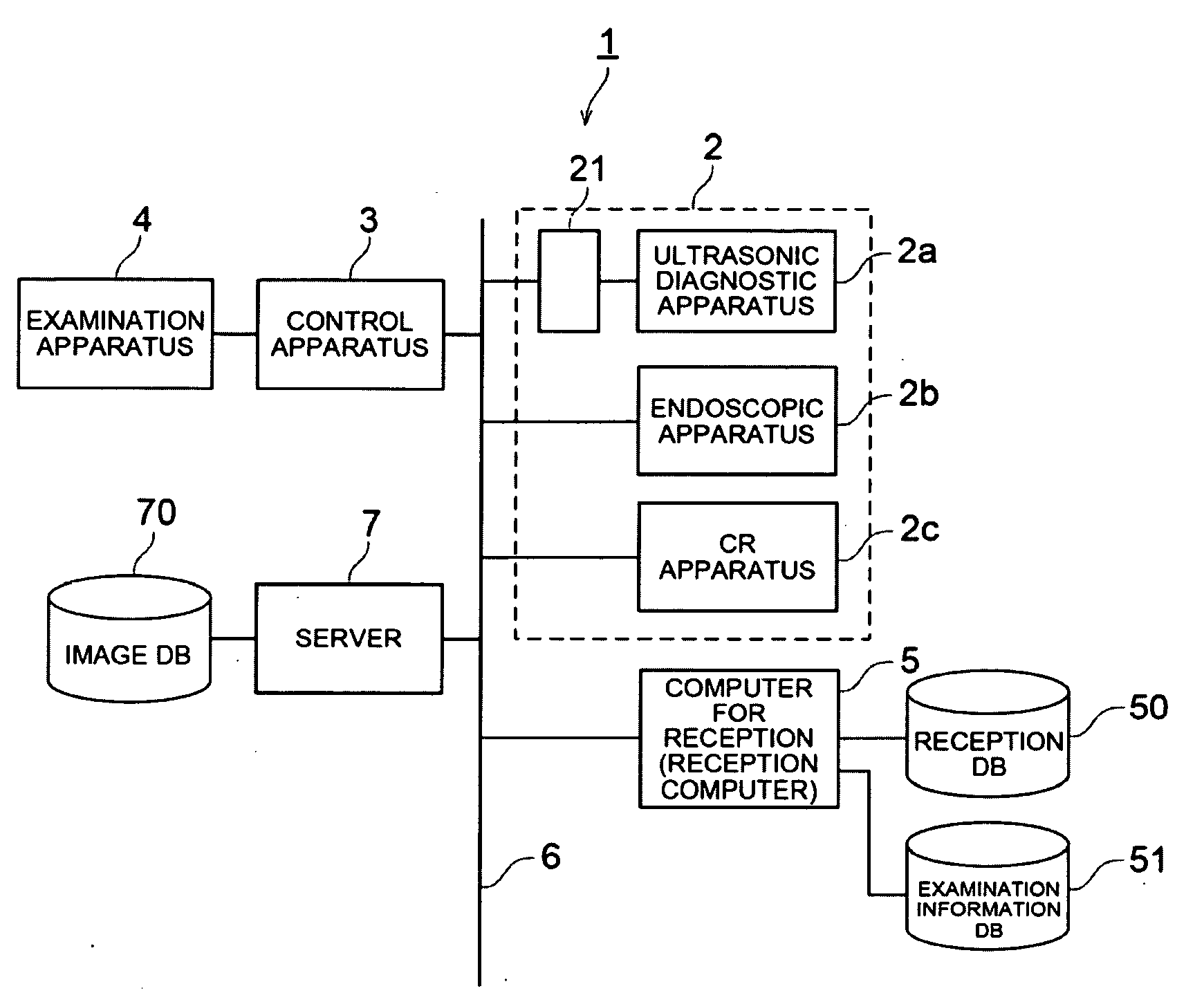
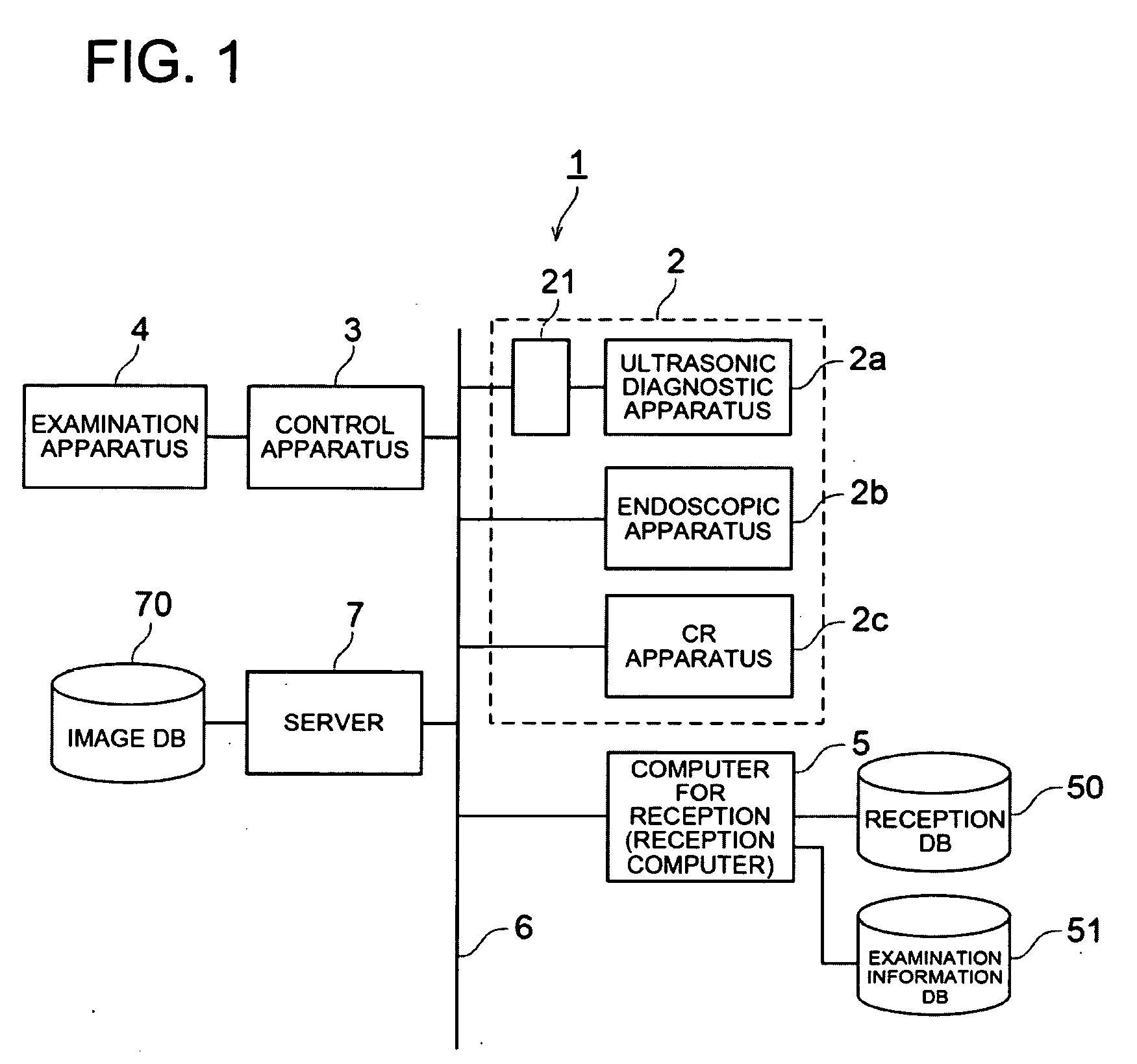
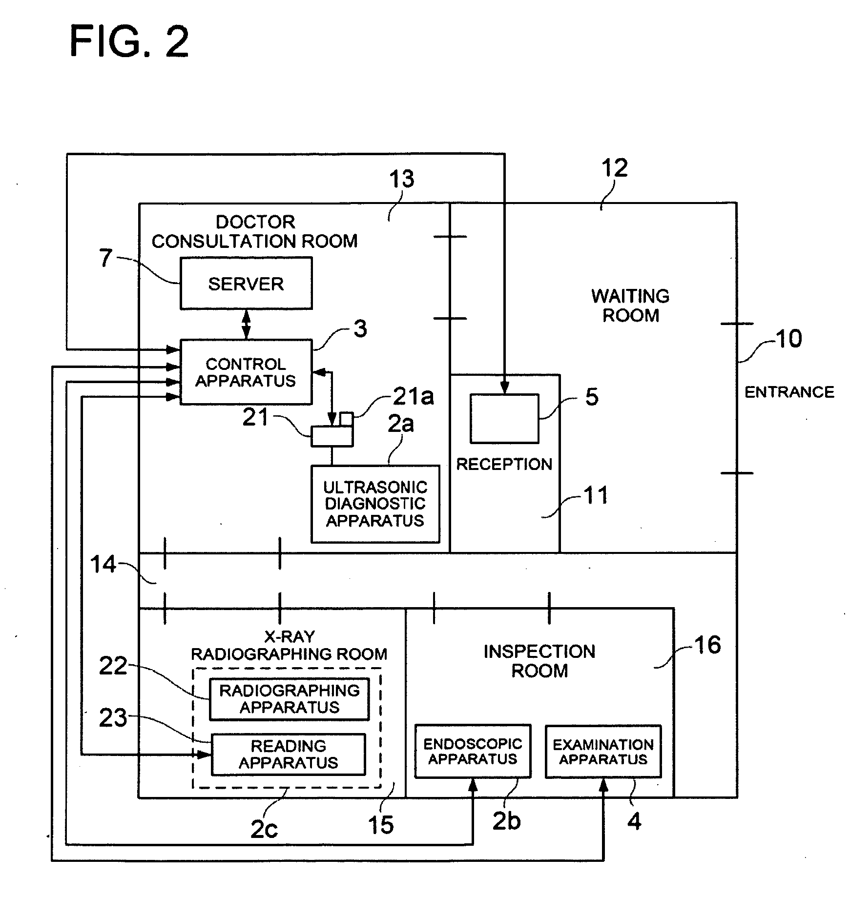
[0118]FIG. 1 shows the system structure of the small-sized diagnostic system 1 to which the medical imaging system of the present invention is applied. FIG. 2 shows the layout of each apparatus in medical facilities wherein the small-sized diagnostic system 1 of FIG. 1 is applied.

[0119]The small-sized diagnostic system 1 is a system applied to small-sized medical facilities of a medical practitioner or in a clinic. As shown in FIG. 1, the small-sized diagnostic system 1 includes an ultrasonic diagnostic apparatus 2a, endoscope apparatus 2b, CR apparatus 2c as the image generating apparatus 2, control apparatus 3 (also called the medical image controlling apparatus), examination apparatus 4, computer for reception 5 (hereinafter referred to as reception c...


PUM


Abstract

A medical imaging system by which in order that image data generated by an image generating apparatus and patient information are efficiently associated with each other while the doctor is examining the patient, an on-line button is blinking on receiving the image data or examination data when a screen showing information on the specified patient is displayed, the received data is automatically associated with the designated patient information and stored in an image DB when the blinking on-line button is depressed, and the received data is temporarily stored in a temporary storage section for storing data waiting for association with the patient information when the blinking on-line button is held depressed long.

Description

FIELD OF THE INVENTION[0001]The present invention relates to a medical imaging system used mainly in small-sized medical facilities, particularly to a medical imaging system capable of displaying a list of a captured image of the examined region of a patient, examination information and / or treatment information.BACKGROUND OF ART[0002]One of the techniques known in the conventional art is a diagnostic system wherein a radiographing technician takes a radiograph of the outpatient as an object of examination using an image generating apparatus such as a CR (Computed Radiography) apparatus or an FPD (Flat Panel Detector), and applies image processing such as gradation processing to ensure that the captured image can be used for diagnosis, whereby the processed image is outputted as a radiograph for interpretation by a doctor.[0003]In such a diagnostic system, diagnosis is carried out by a plurality of persons in charge of different functions such as a person in charge of receiving an ou...

Claims


Application Information

Patent Timeline
IPC IPC(8): A61B5/05G06Q50/00G16H10/60G16H30/20
CPCG06F19/321G06F19/3487A61B6/4494H04L67/12G06Q50/24G16H15/00G16H30/20
Inventor SHIIBASHI, TAKAO
Owner KONICA MINOLTA MEDICAL & GRAPHICS INC
Learn More