Method and Apparatus for Creating Visual Effects on Grass

Active Publication Date: 2009-02-26
DAVIS PETE J
View PDF23 Cites 8 Cited by
  • Summary
  • Abstract
  • Description
  • Claims
  • Application Information

AI Technical Summary

Benefits of technology

[0010]Accordingly, the invention generates detailed images and imprints these images on natural or artificial lawns and fields, covered areas such as sports fields, and landscapes. As a result, images imprinted on such surfaces in accordance with the invention, have a high degree of resolution and contrast, such that they are readily used as a medium for marketing products, general advertising, and artistic beautification.
[0012]One embodiment of the invention uses specialized lawn and field equipment that is known to provide sufficient resolution and that has the potential to produce highly detailed features. This invention exploits the full potential of such equipment by eliminating the operator as a variable during creation and imprinting of the pattern. Thus, in the invention patterns are translated into instructions which operate a computer or other device. Individual patterning implements receive and react to these instructions. Patterning errors are reduced by using equipment position tracking and guidance systems. One embodiment of the invention provides mechanical hardware, software, and processes that control the above effects to produce visual contrast, and thus efficiently and accurately imprint highly detailed images onto lawns, grass, or turf fields.
[0014]The patterning equipment described above is impelled by a mechanical means along the turf, for example by towing the patterning equipment with a tractor. The patterning equipment can comprise, for example, grass cutting or bending implements. Typical grass cutting means include, e.g. spinning blades, and grass bending means include, e.g. rollers. High resolution patterning of the turf is obtained by automating the action of the individual implements. In a manner similar to that of a dot matrix printer, individual pixels or contrast swaths are imprinted onto a turf using this technique. Although simple, this computer controlled dot matrix approach is far superior to the current low-resolution system where the skill of the operator controls the quality of the pattern.
[0017]The imprinting processes disclosed herein can provide entertainment as well. For example, the dynamic qualities of the field printing process can be entertaining for spectators during pre-event seating and intermission. Computer generated programs can be used to control the imprinting of the field in an arranged sequence, thus providing a strategically orchestrated, paced unveiling of the image. Further, the invention makes it possible to imprint multiple layers by dividing-up artistic components and imprinting them sequentially. For example, a first layer may contain a base, while subsequent layers provide sequences of higher detail.

Problems solved by technology

The state of the art has heretofore not allowed for the creation of precise, consistent, and repeatable patterns.
Attempts to produce improved detail have been limited by the equipment's fixed width and lack of ability to create details or contrast with any degree of precision.
One limitation of the prior art is that the quality of patterning depends on how precisely the operator is able to guide the equipment.
The quality of the patterning often suffers from accumulated ranging errors.
Further degradation occurs as the patterning area increases and when there is an absence of line-of-sight feedback to the operator.
Thus, existing lawn and turf maintenance equipment and operations used to produce patterns do not have sufficient resolution and precision to produce highly detailed artwork, such as pictures, corporate logos, and script.

Method used


Image

  • Method and Apparatus for Creating Visual Effects on Grass
  • Method and Apparatus for Creating Visual Effects on Grass
  • Method and Apparatus for Creating Visual Effects on Grass

Examples


Embodiment Construction

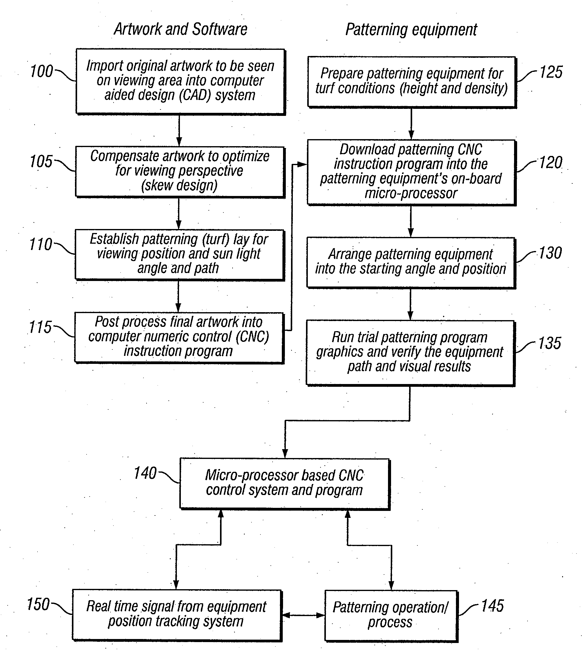
[0031]A method and apparatus for imprinting high resolution images onto fields, such as sports fields and landscapes is disclosed. In one embodiment, precise and consistent lawn and field patterning is accomplished by use in combination of a global positioning system; a processor for generating a desired pattern which is translated into patterning instructions; and a patterning implement which is used for generating detailed patterns and for imprinting said patterns on any of natural or artificial lawns and fields, covered areas, and landscapes. The patterning implement comprises a plurality of independent printing mechanisms incorporated within said patterning implement, each of the independent printing mechanisms coupled to receive patterning instructions from the processor and operate selectively in response thereto. The invention also comprises means for guiding the patterning implement to position it along a desired path at least in part with information from said global positi...


PUM


Abstract

A method and apparatus for imprinting high resolution images onto fields, such as sports fields and landscapes is disclosed. In one embodiment, precise and consistent lawn and field patterning is accomplished by use in combination of a global positioning system; a processor for generating a desired pattern which is translated into patterning instructions; and a patterning implement which is used for generating detailed patterns and for imprinting said patterns on any of natural or artificial lawns and fields, covered areas, and landscapes. The patterning implement comprises a plurality of independent printing mechanisms incorporated within said patterning implement, each of the independent printing mechanisms coupled to receive patterning instructions from the processor and operate selectively in response thereto. The invention also comprises means for guiding the patterning implement to position it along a desired path at least in part with information from said global positioning system; and means for individually controlling each of said independent printing mechanisms incorporated within said patterning implement responsive to said patterning instructions and in coordination with positioning of said patterning implement along said desired path.

Description

BACKGROUND OF THE INVENTION[0001]1. Field of the Invention[0002]The invention relates to a method and apparatus for imprinting high resolution images onto natural or artificial lawns and fields, covered areas such as sports fields, and landscapes, for example to provide a new or enhanced media for marketing, advertising, and beautification.[0003]2. Discussion of the Prior Art[0004]Certain types of lawn patterning techniques have been used in the past to enhance the visual characteristics of sports fields, and commercial and residential landscapes. These patterning techniques are produced with lawn maintenance equipment, such as mowers that are piloted by grounds keepers. The state of the art has heretofore not allowed for the creation of precise, consistent, and repeatable patterns. Thus, the conception and execution of a patterning procedure has been more art than science, and the outcome of the pattern has thus been largely dependent upon the operator's skill and the characteristi...

Claims


Application Information

Patent Timeline
IPC IPC(8): G06F17/00
CPCG06Q30/0241B44C1/222
Inventor DAVIS, PETE J.
Owner DAVIS PETE J
Why Eureka
Try Eureka