


Quick Research
Generate reliable direction feasibility study reports for your R&D in just a few steps.

Technical Q&A
Discover and master advanced knowledge NOW. Basics, ideas, possibilities, all at once.

Find Solutions
As an expert in R&D theories, this can generate solutions to your technical problems instantly.

Evaluate Feasibility
Analyze your overall solution with one click, know your potential R&D risks in advance.

Monitor Landscape
Get weekly tech updates, stay abreast of the latest tech innovations and key insights.
High-hardness carbon coating
a carbon coating and high-hardness technology, applied in the direction of vacuum evaporation coating, coating, sputtering coating, etc., to achieve the effect of excellent abrasion resistance and low friction
- Summary
- Abstract
- Description
- Claims
- Application Information
AI Technical Summary
Benefits of technology
Problems solved by technology
Method used
Image

Examples
first embodiment
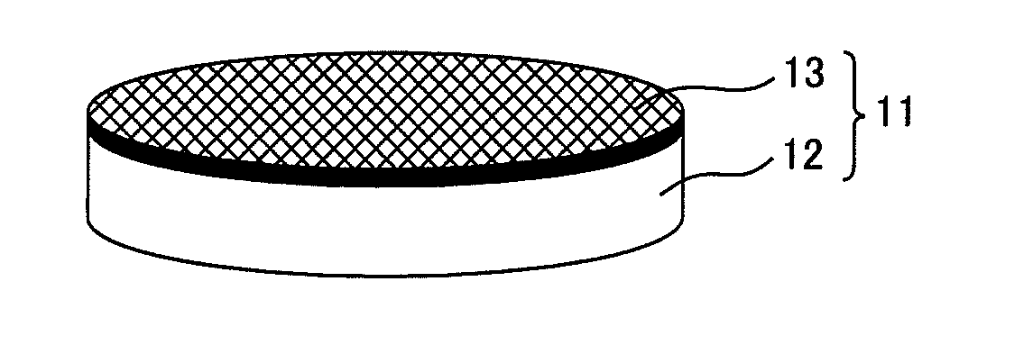
[0050]Carburizing was carried out to make the surface hardness of the disk substrate 12 composed of a metal alloy (chromium molybdenum steel) containing Fe, Cr and Mo to be a Rockwell hardness scale C (HRC) value of 58 or more and dressing was carried out to achieve a surface roughness (Ra) of 0.1 μm or less.
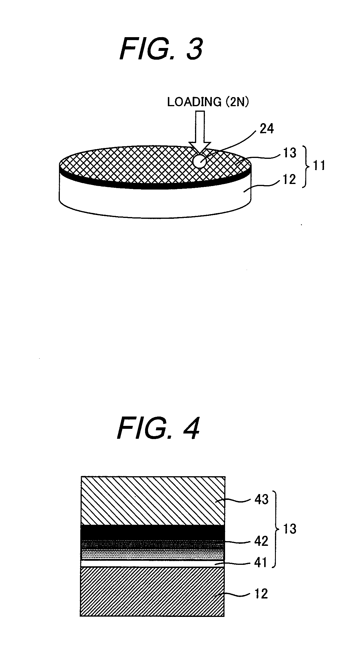
[0051]After that, the coating 13 was formed by using the unbalanced magnetron sputtering method during introduction of an inert gas and a hydrocarbon gas. As shown in FIG. 4, the coating 13 has a Cr interlayer 41, a surface layer 43, and a gradient layer 42 between the Cr interlayer 41 and the surface layer 43. When the surface layer 43 was formed, a power of 3.0 kW and 0.05 kW were input to a C target and a MoS2 target, respectively.
[0052]After formation of the coating 13, the concentration of each Mo, S, O and C elements was putatively measured by using XPS analysis. The sum of the concentration of all elements of Mo, S, O and C was assumed to be 100 at %. As a result, it was ...
second embodiment
[0083]Carburizing was carried out to make the surface hardness of the disk substrate 12 composed of a chromium molybdenum steel be an HRC of 58 or more and dressing was carried out to achieve an Ra of 0.1 μm or less. After that, the coating 13 was formed by using the unbalanced magnetron sputtering method during introduction of an inert gas and a hydrocarbon gas. As shown in FIG. 4, the coating 13 has a Cr interlayer 41, a surface layer 43, and a gradient layer 42 between the Cr interlayer 41 and the surface layer 43. When the surface layer 43 was formed, a power of 3.0 kW and 0.1 kW were input to the C target and MoS2 target, respectively.
[0084]After formation of the coating 13, the concentration of each Mo, S, O and C element was putatively measured by using XPS analysis.
[0085]The sum of the concentrations of all elements of Mo, S, O and C was assumed to be 100 at %.
[0086]As a result, it was confirmed that Mo: 6.0 at %, S: 2.8 at %, O: 8.8 at % and C: 82.4 at %.
[0087]In addition, ...
PUM
| Property | Measurement | Unit |
|---|---|---|
| friction coefficients | aaaaa | aaaaa |
| friction coefficient | aaaaa | aaaaa |
| friction coefficient | aaaaa | aaaaa |
Abstract
Description
Claims
Application Information
 - R&D Engineer
- R&D Manager
- IP Professional
- Industry Leading Data Capabilities
- Powerful AI technology
- Patent DNA Extraction
Browse by: Latest US Patents, China's latest patents, Technical Efficacy Thesaurus, Application Domain, Technology Topic, Popular Technical Reports.
© 2024 PatSnap. All rights reserved.Legal|Privacy policy|Modern Slavery Act Transparency Statement|Sitemap|About US| Contact US: help@patsnap.com