

Gated Quantum Resonant Tunneling Diode Using CMOS Transistor with Modified Pocket and LDD Implants
a gated quantum resonant and tunneling diode technology, applied in the field of integrated circuits, can solve problems such as the problem of integrating quantum well resonant tunneling diodes in silicon integrated circuits which allow operation at room temperatur
- Summary
- Abstract
- Description
- Claims
- Application Information
AI Technical Summary
Problems solved by technology
Method used
Image

Examples
first embodiment
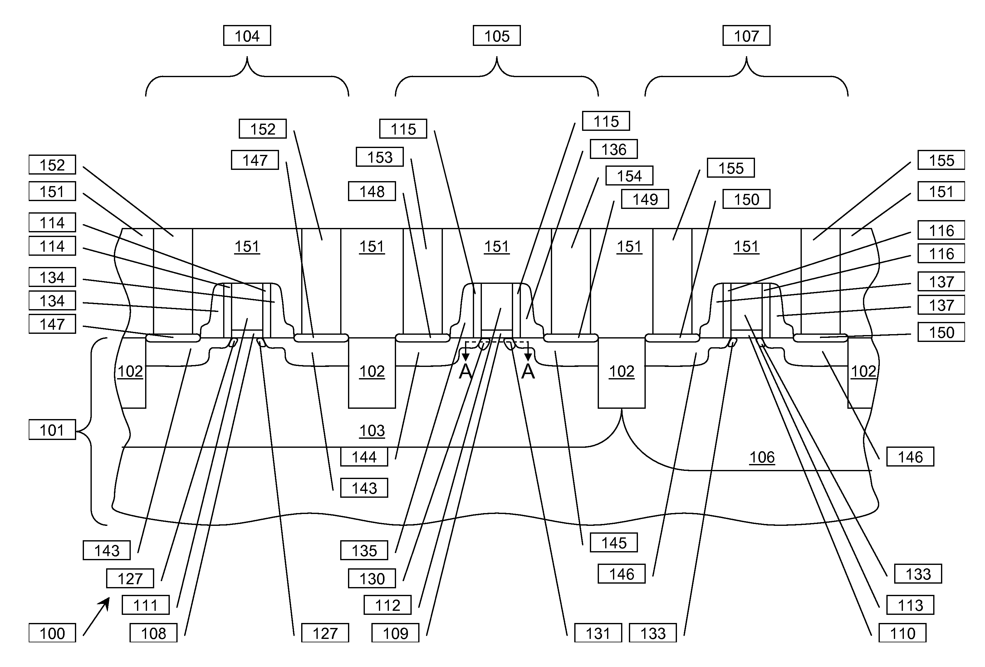
[0040]FIG. 2A through 2C are energy band diagrams of GRTD elements as recited in the first embodiment discussed in reference to FIG. 1A through FIG. 1D, for example along section line A-A in FIG. 1D. Referring to FIG. 2A, a GRTD gate is biased with respect to a p-well containing the GRTD to form an n-type quantum well in a region below the GRTD gate dielectric layer. A conduction band edge (200) is plotted through an n-type GRTD source region (202), an n-type GRTD source side LDD region (204), a p-type GRTD source halo region (206), a quantum well region (208), a p-type GRTD drain halo region (210), an n-type GRTD drain side LDD region (212) and an n-type GRTD drain region (214). The GRTD source region (202) and the GRTD drain region (214) are biased at zero volts with respect to the p-well containing the GRTD. The GRTD source region (202) and GRTD drain region (214) are degenerately doped, causing the conduction band edge (200) to be lower in energy than a Fermi level (216). A p-ty...
second embodiment
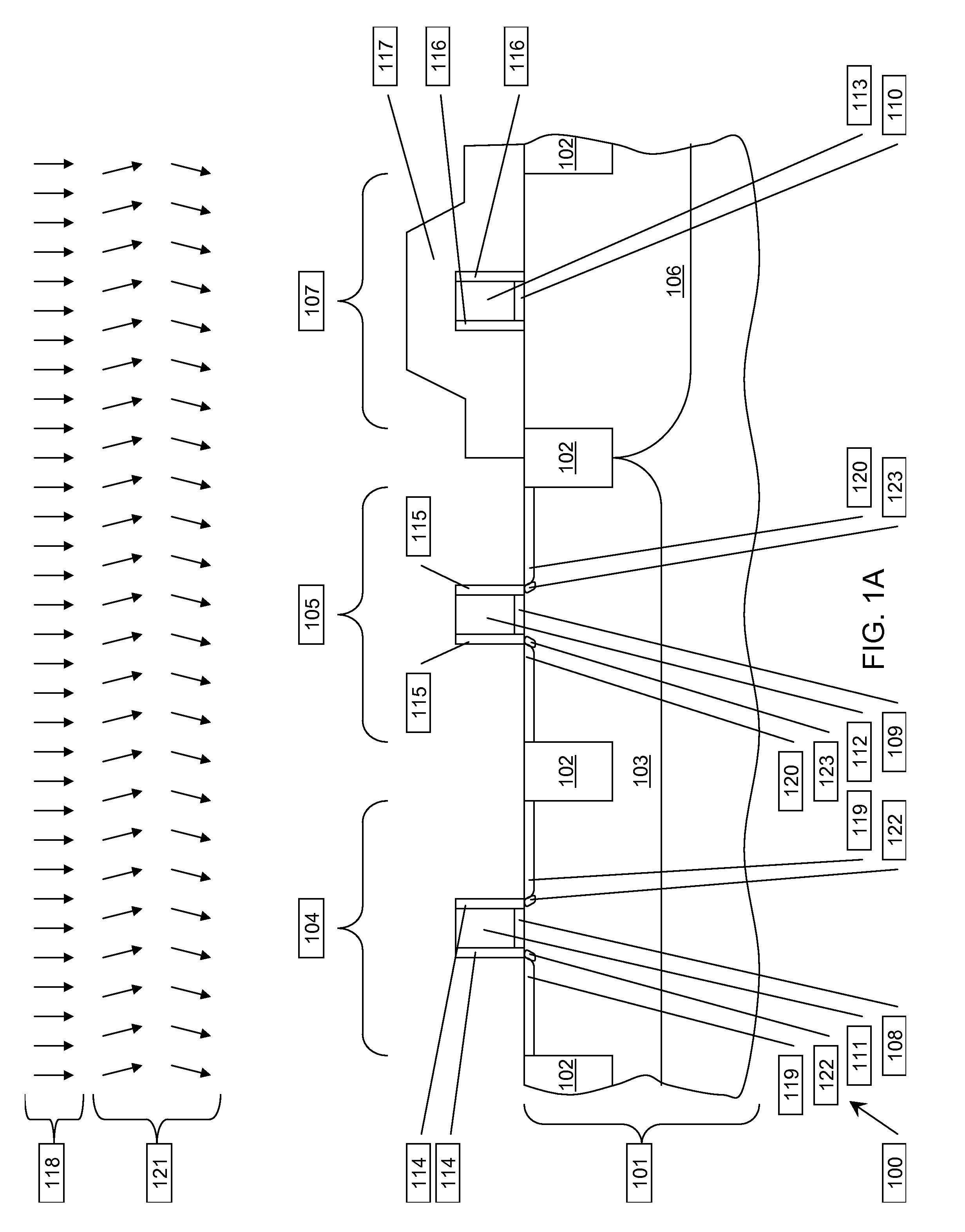
[0048]FIG. 7A through FIG. 7C are cross-sections of a CMOS IC including a GRTD formed according to the instant invention, depicted in successive stages of fabrication. Referring to FIG. 7A, the IC (700) is formed in a semiconductor substrate (701) with the properties described in reference to FIG. 1A. Elements of field oxide (702) are formed in the substrate (701) by an STI process, separating an NMOS region (703), a GRTD region (704) and a PMOS region (705). A p-well (706) is formed in the substrate (701) in the NMOS region (703) and the GRTD region (704) as described in reference to FIG. 1A. Similarly, an n-well (707) is formed in the substrate (701) in the PMOS region (705) as described in reference to FIG. 1A. An NMOS gate dielectric layer (708), a GRTD gate dielectric layer (709) and a PMOS gate dielectric layer (710) are formed on top surfaces of the substrate (701), with the properties described in reference to FIG. 1A, in the NMOS region (703), the GRTD region (704) and the ...
third embodiment
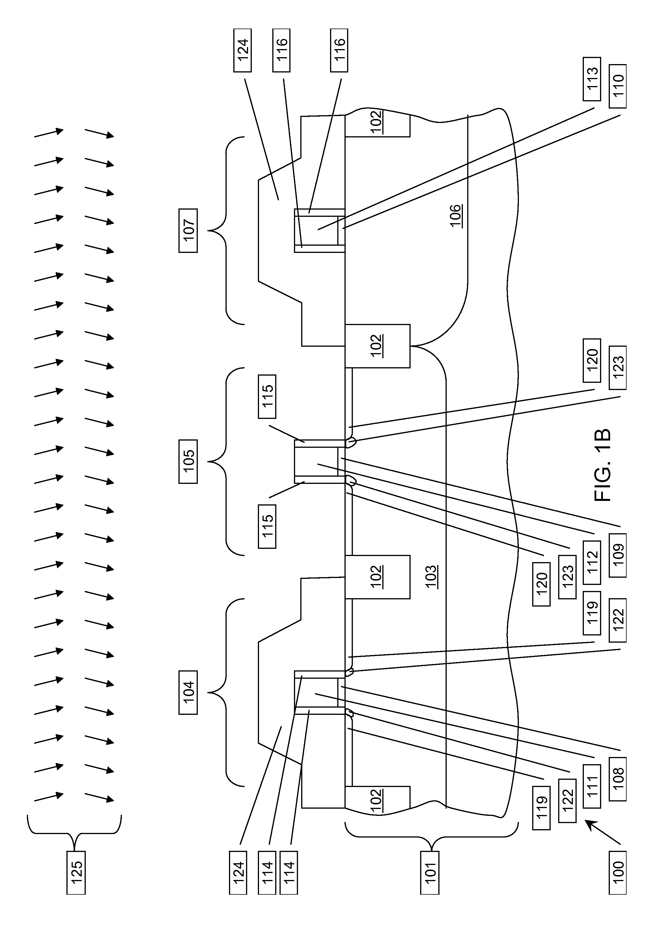
[0062]FIG. 12A through FIG. 12C are cross-sections of a CMOS IC including a GRTD formed according to the instant invention, depicted in successive stages of fabrication. Referring to FIG. 12A, the IC (1200) is formed in a semiconductor substrate (1201) with the properties described in reference to FIG. 1A. Elements of field oxide (1202) are formed in the substrate (1201) by an STI process, separating an NMOS region (1203), a GRTD region (1204) and a PMOS region (1205). A p-well (1206) is formed in the substrate (1201) in the NMOS region (1203) and the GRTD region (1204) as described in reference to FIG. 1A. Similarly, an n-well (1207) is formed in the substrate (1201) in the PMOS region (1205) as described in reference to FIG. 1A. An NMOS gate dielectric layer (1208), a GRTD gate dielectric layer (1209) and a PMOS gate dielectric layer (1210) are formed on top surfaces of the substrate (1201), with the properties described in reference to FIG. 1A, in the NMOS region (1203), the GRTD...
PUM
 Abstract
Description
Claims
Application Information