
CPP device with improved current confining structure and process

a technology of current confining structure and cpp, which is applied in the field of ccp cpp gmr devices, can solve the problems of easy compromise of cu purity, and achieve the effects of improving overall performance, easy adaptability to incorporation, and improving dr/r

Inactive Publication Date: 2009-03-05
HEADWAY TECH INC
View PDF11 Cites 17 Cited by
  • Summary
  • Abstract
  • Description
  • Claims
  • Application Information

AI Technical Summary

Benefits of technology

[0013]It has been an object of at least one embodiment of the present invention to provide a Confined Current Path structure in which the copper conducting filaments are free of oxygen contamination.
[0014]Another object of at least one embodiment of the present invention has been that said structure, when used in the context of a GMR or MTJ device, have associated magnetic layers, such as the pinned and free layers, that are free of oxygen contamination.
[0016]A further object of at least one embodiment of the present invention has been that said process be easily adaptable for incorporation as part of processes currently in use for the manufacture of GMR and MTJ devices.
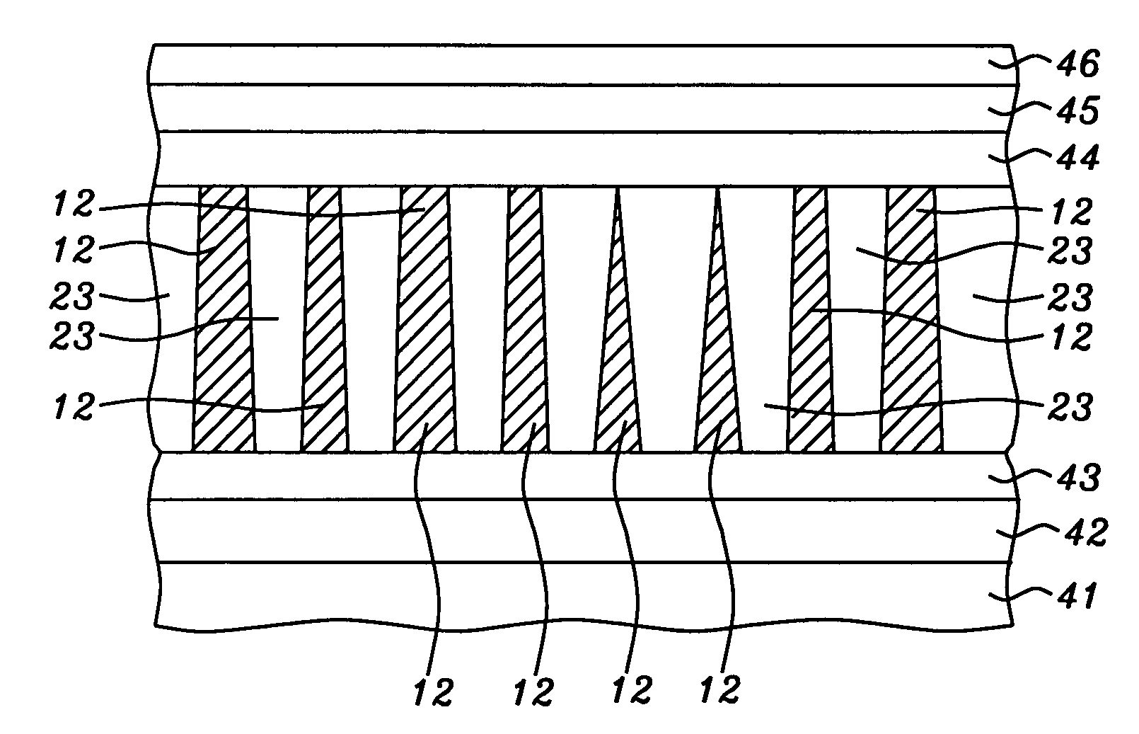
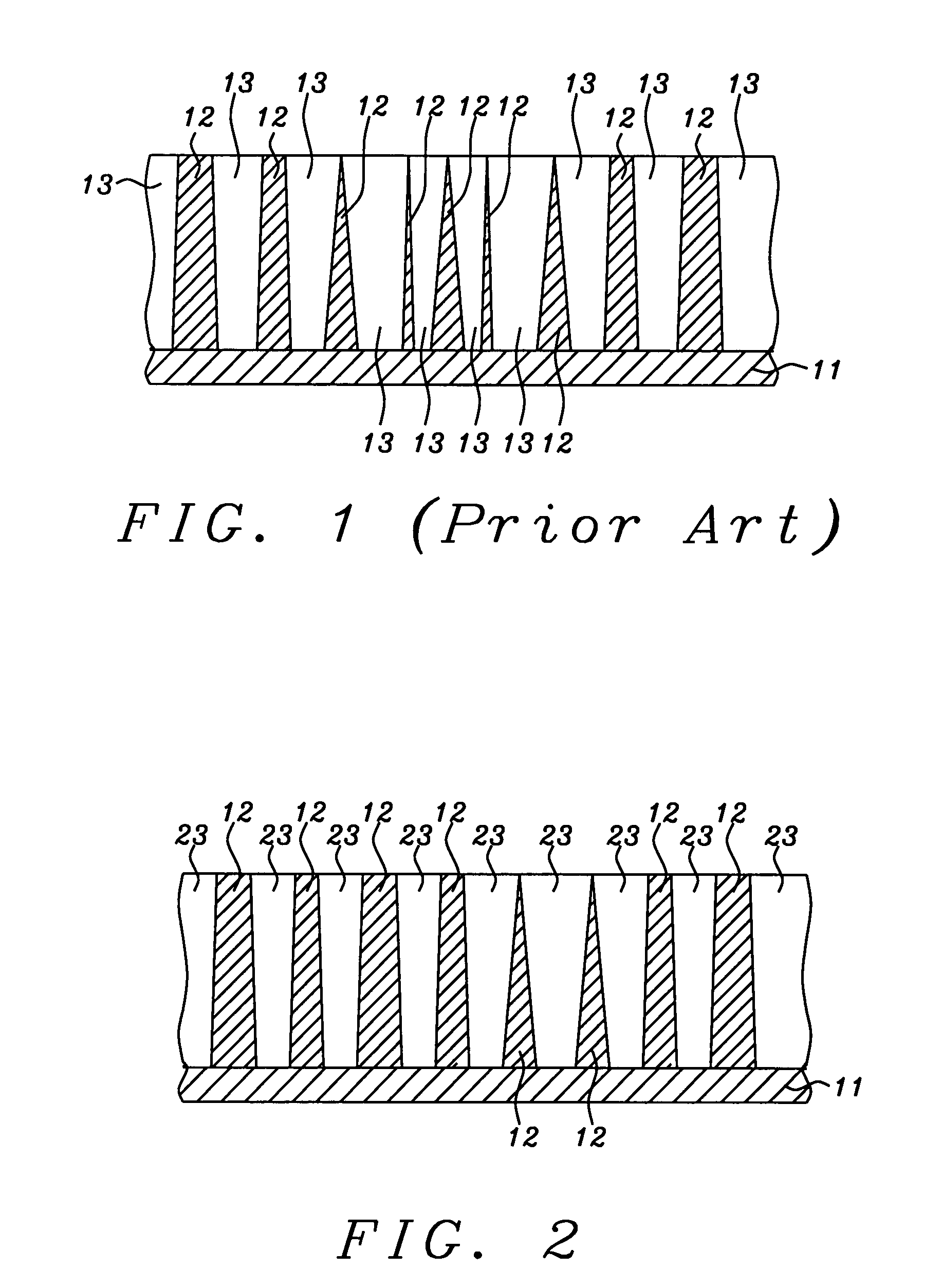
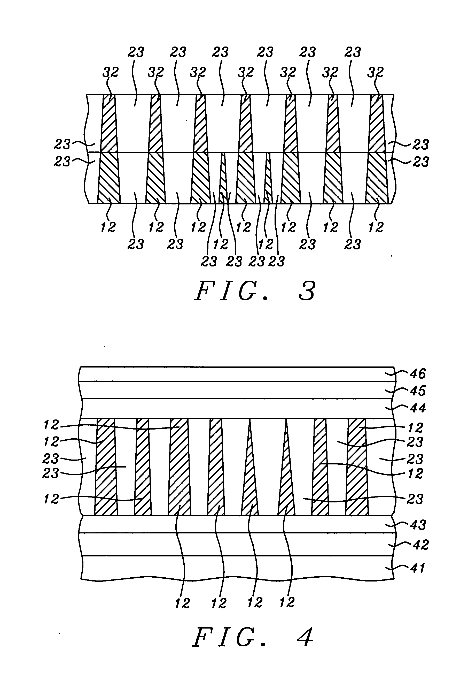
[0017]These objects have been achieved by the use of plasma nitridation, in place of plasma oxidation, for the formation of the CCP layer. Al, Mg, Hf, etc. all form insulating nitrides under these conditions. By maintaining the structure at a temperature of at least 150° C. during the plasma nitridation we ensure that no copper nitride can form. Additionally, unintended oxidation by molecular oxygen of the exposed magnetic layers (mainly the pinned and free layers) is also avoided. The net result is better dR / R and better overall performance.

Problems solved by technology

However, for the metal CPP case, the CPP GMR ratio remains at a rather low value; for CCP-CPP schemes, since the current path is confined to Cu metal channels that are connected through an oxide matrix (AlOx, TiO2, or MgO layers) [5], the Cu purity is easily compromised during the insulator formation process, making the latter critical to ensuring a high MR ratio.

Method used


Image

  • CPP device with improved current confining structure and process
  • CPP device with improved current confining structure and process
  • CPP device with improved current confining structure and process

Examples


Embodiment Construction

[0022]In conventional CPP devices, a Cu spacer is used either as a full film layer for metal CPP or as a confined metal path in the CCP-CPP scheme. In the metal CPP case, since the resistance of Cu is very small, the CPP dR / R is shunted away to a small value. In the CCP-CPP case, the Cu metal path is formed and confined within an insulating template, typically AlOx or MgO, so that ARA can be enhanced quite significantly.

[0023]Insulator formation is generally accomplished using ion-assisted oxidation (IAO), such as plasma oxidation, radical oxidation, ozone oxidation or even natural oxidation. It is critical to preserve the copper purity during this step if one is to achieve the best possible MR ratio. Thus, the insulator formation process should result only in the formation of the insulator layer without oxidizing the Cu metal path or any other critical layers such as the free and AP1 (pinned reference) layers. In the prior art, during the oxidation of Al, Mg or the like materials, ...


PUM

PropertyMeasurementUnit
thicknessaaaaaaaaaa
thicknessaaaaaaaaaa
thicknessaaaaaaaaaa

Abstract

Plasma nitridation, in place of plasma oxidation, is used for the formation of a CCP layer. Al, Mg, Hf, etc. all form insulating nitrides under these conditions. Maintaining the structure at a temperature of at least 150° C. during plasma nitridation and / or performing post annealing at a temperature of 220° C. or higher, ensures that no copper nitride can form. Additionally, unintended oxidation by molecular oxygen of the exposed magnetic layers (mainly the pinned and free layers) is also avoided

Description

[0001]This application is related to application Ser. No. 11 / 704,399, filed Jun. 3, 2007, herein incorporated, by reference, in its entirety.FIELD OF THE INVENTION[0002]The invention relates to the general field of CCP CPP GMR devices with particular reference to the composition and formation of the current confining layer.BACKGROUND OF THE INVENTION[0003]Current perpendicular to plane (CPP) giant magnetoresistance (GMR) based magnetic heads are considered as promising candidates for achieving a recording density of over 200 Gb / in2 [1-2]. In a CPP GMR head structure a bottom synthetic spin valve type film stack is employed for biasing reasons, and a CoFe / NiFe composite free layer is conventionally used following the experience with Current in Plane (CIP) GMR devices. It has already been demonstrated [3] that by laminating CoFe AP1 layers with thin Cu, CPP GMR performance can be improved. An example of a metallic CPP spin valve structure is:Seed / AFM / AP2 / Ru / [CoFeCu] / Cu30 / [CoFe / NiFe] / c...

Claims


Application Information

Patent Timeline
Patent Type & Authority Applications(United States)
IPC IPC(8): G11B5/33B05D5/12
CPCB82Y10/00B82Y25/00G01R33/093Y10T29/49021G11B5/3909G11B2005/3996G11B5/39G11B5/3906
Inventor ZHANG, KUNLIANGLI, MINLIU, YUE
Owner HEADWAY TECH INC
Learn More