Electrostatic chuck

Inactive Publication Date: 2009-03-05
SHINKO ELECTRIC IND CO LTD
View PDF1 Cites 35 Cited by
  • Summary
  • Abstract
  • Description
  • Claims
  • Application Information

AI Technical Summary

Benefits of technology

[0020]When doing this, even when gas holes are formed in a peripheral portion of the electrostatic chuck, the base portion and the chuck function portion in the vicinity of the gas holes are directly bonded to each other with the adhesive layers and thus makes the adhesion strength therebetween higher. According

Problems solved by technology

However, in an electrostatic chuck with a heater composed by adhering a chuck function portion in which a heater electrode and an ESC electrode are built, on a base portion with an adhesive layer, the adhesive layer is too thin to have sufficiently good heat insulation proper

Method used


Image

  • Electrostatic chuck
  • Electrostatic chuck
  • Electrostatic chuck

Examples


first embodiment

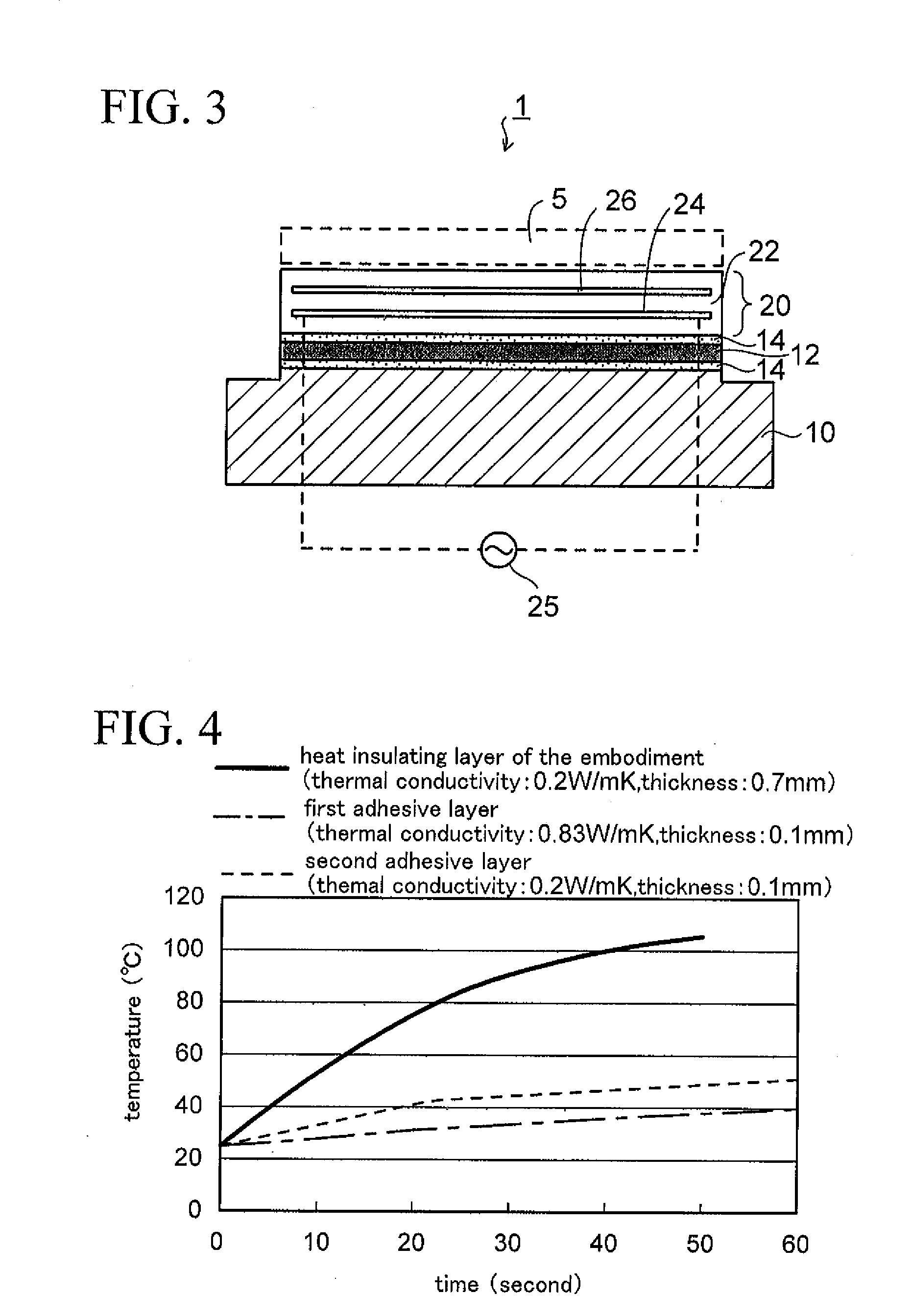
[0040]FIG. 3 is a cross-sectional view showing an electrostatic chuck of a first embodiment of the present invention.

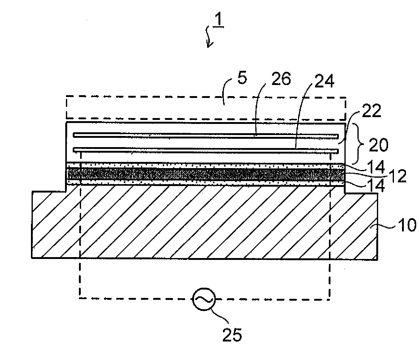
[0041]As shown in FIG. 3, in the electrostatic chuck 1 of the first embodiment, a chuck function portion 20 is provided on a base portion 10 via a heat insulating layer 12 disposed therebetween. An adhesive layer 14 is formed under the lower surface of the heat insulating layer 12, and the base portion 10 is bonded onto the heat insulating layer 12 with the adhesive layer 14. In addition, another adhesive layer 14 is formed on the upper surface of the heat insulating layer 12, and the chuck function portion 20 is bonded onto the heat insulating layer 12 with the adhesive layer 14.

[0042]As described above, the chuck function portion 20 is fixed onto the base portion 10 via the heat insulating layer 12 on the both surface sides of which the adhesive layers 14 is formed.

[0043]As a material for the base portion 10, aluminum (or alloys thereof) should preferably be used, b...

second embodiment

[0059]FIG. 5 is a cross-sectional view showing an electrostatic chuck of a second embodiment of the present invention. FIG. 6 is a plan view showing a state of openings in a heat insulating layer of the electrostatic chuck of FIG. 5. In the following description of the second embodiment, the same elements as those of the first embodiment are denoted by the same reference numerals, and description thereof will be omitted.

[0060]In the electrostatic chuck 1 (FIG. 3) of the aforementioned first embodiment, the sheet-like heat insulating layer 12 is employed without being processed, and the adhesive layers are formed on the both surface sides of the heat insulating layer 12, and the chuck function portion 20 and the base portion 10 are bonded via the heat insulating layer 12.

[0061]The heat insulating layer 12 which is formed of a material such as silicone rubber or fluorine rubber has relatively poor adhesion property to other members. Accordingly in the bonding method of the first embod...


PUM


Abstract

An electrostatic chuck of the invention includes a base portion; a heat insulating layer bonded onto the base portion; and a chuck function portion bonded on the heat insulating layer and composed by providing a heater electrode and an electrostatic chuck (ESC) electrode in a ceramic substrate portion. Adhesive layers are respectively provided on the both surface sides of the heat insulating layer. In the case where the base portion and the chuck function portion are bonded together with high adhesion strength, openings are formed in the heat insulating layer and are filled with the adhesive layers.

Description

CROSS-REFERENCE TO RELATED APPLICATIONS[0001]This application is based on and claims priority of Japanese Patent Application No. 2007-222470 filed on Aug. 29, 2007, the entire contents of which are incorporated herein by reference.BACKGROUND OF THE INVENTION[0002]1. Field of the Invention[0003]The present invention relates to an electrostatic chuck, more specifically to an electrostatic chuck with a heater to be employed in various manufacturing apparatuses in order to control a temperature of a wafer during a semiconductor wafer process or the like.[0004]2. Description of the Related Art[0005]Heretofore, a manufacturing apparatus used in a semiconductor wafer process or the like (a plasma chemical vapor deposition (CVD) apparatus, a dry etching apparatus or the like) is provided with an electrostatic chuck onto which a wafer is placed and electrostatically chucked so that a temperature of the wafer can be controlled during various processes. For example, in the dry etching apparatu...

Claims


Application Information

Patent Timeline
IPC IPC(8): H01L21/683
CPCH01L21/67103H02N13/00H01L21/6833H01L21/68
Inventor YONEKURA, HIROSHIYOSHIKAWA, TADAYOSHI
Owner SHINKO ELECTRIC IND CO LTD
Why Eureka
Try Eureka