

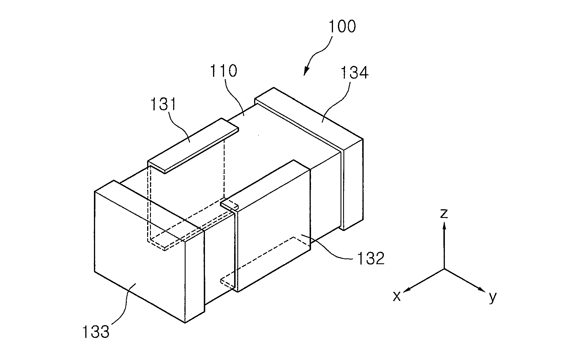
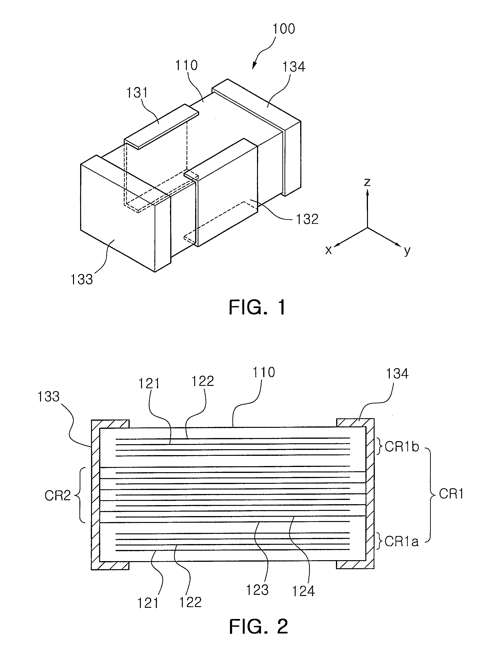
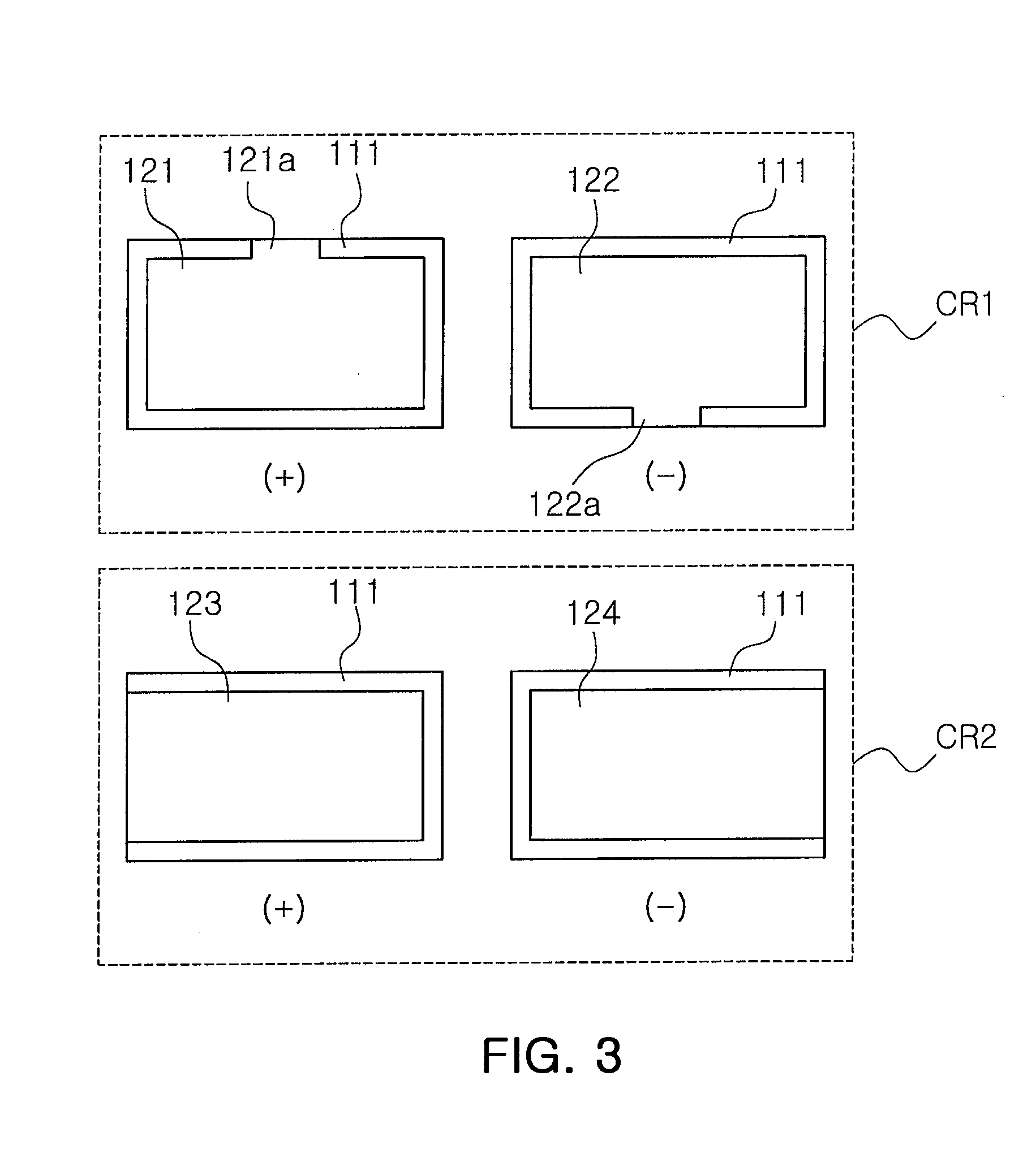
Multilayer chip capacitor, circuit board apparatus having the capacitor, and circuit board
a multi-layer chip and capacitor technology, applied in the direction of fixed capacitor details, sustainable manufacturing/processing, final product manufacturing, etc., can solve the problems of increasing increasing the current consumption of the mpu and decreasing the operation voltage, and increasing the difficulty of suppressing the noise of the supply dc voltage within a certain rang
- Summary
- Abstract
- Description
- Claims
- Application Information
AI Technical Summary
Benefits of technology
Problems solved by technology
Method used
Image

Examples
examples 1 and 2
[0087]FIG. 9 is a graph illustrating frequency vs. impedance (f-z) characteristics of the multilayer chip capacitor according to one exemplary embodiment of the present invention. The graph of FIG. 9 shows the results of measuring frequency-impedance of samples having the capacitor and the circuit board apparatus according to the exemplary embodiments of FIGS. 1 to 4.
[0088]Particularly, a sample of Example 1 as shown in FIG. 9 conforms to a multilayer chip capacitor with 1608 size (1.6 mm×0.8 mm) and 4 terminals having 10 μF capacitance. The capacitance of the first capacitor unit is 0.52 μF, and the capacitance of the second capacitor unit is 9.48 μF. Also, the ESL and ESR of the first capacitor unit are 300 pH and 60 mΩ, respectively, and the actual ESL and ESR (L2′, R2′ as shown in FIG. 6) of the second capacitor unit to which the coupling conductor lines are added in series are 700 pH and 35 mΩ, respectively. Regardless of the large capacitance difference in the first and second...
examples 3 and 4
[0117]FIG. 23 is a graph illustrating frequency vs. impedance (f-z) characteristics of the multilayer chip capacitor according to one exemplary embodiment of the present invention. The graph of FIG. 23 shows the results of measuring frequency-impedance of samples having the capacitor and the circuit board apparatus according to the exemplary embodiments of FIGS. 15 to 18.
[0118]Particularly, a sample of Example 3 as shown in FIG. 23 conforms to a multilayer chip capacitor with 1608 size and 10 terminals having 2.2 μF capacitance. The capacitance of the first capacitor unit is 0.4 μF, and the capacitance of the second capacitor unit is 1.8 μF. Also, the ESL and ESR of the first capacitor unit are 110 pH and 43 mΩ, respectively, and the actual ESL and ESR (L2′, R2′ as shown in FIG. 18) of the second capacitor unit to which the coupling conductor lines are added in series are 700 pH and 46 mΩ, respectively.
[0119]As the results of measuring the frequency-impedance of the above-mentioned ...
PUM
 Abstract
Description
Claims
Application Information