Optical fiber

a technology of optical fiber applied in the field of optical fiber, can solve the problems of unfavorable sbs, unfavorable sbs for optical fiber devices used for optical signal control, and inconvenient longitudinal direction of optical properties, so as to increase refractive index and acoustic wave velocity, and reduce acoustic wave velocity

Active Publication Date: 2009-03-05
FURUKAWA ELECTRIC CO LTD
View PDF9 Cites 7 Cited by
  • Summary
  • Abstract
  • Description
  • Claims
  • Application Information

AI Technical Summary

Benefits of technology

[0012]Moreover, according to still another aspect of the present invention, there is provided an optical fiber made of silica-based material. The optical fiber includes a core formed at a center of the optical fiber; and a cladding formed around the core. A nonlinear

Problems solved by technology

The SBS is unfavorable because it disturbs light propagation in the optical fiber.
The SBS is also unfavorable for an optical fiber device used for optical signal control based on the nonlinear optical effects.
However, although the SBS can be suppressed with the increased SBS threshold in such an optical fiber with the optical properties varied in the longitudinal direction, there is a drawback that the optical properties are not constant in the longitudinal direction.

Method used


Image

  • Optical fiber
  • Optical fiber
  • Optical fiber

Examples


first embodiment

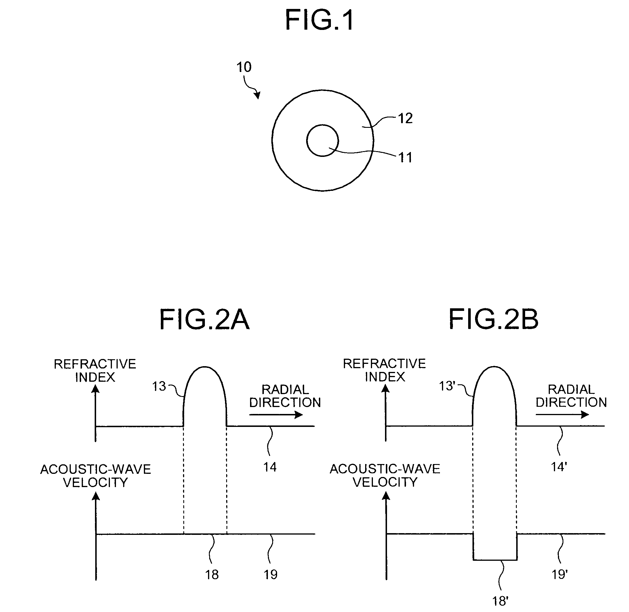
[0025]FIG. 1 is a schematic diagram of an optical fiber 10 according to the The optical fiber 10 is a silica-based single-mode optical fiber that includes a core 11 and a cladding 12 formed around the core 11.

[0026]The core 11 is doped with GeO2 that increases a refractive index and decreases an acoustic-wave velocity by 22 wt % and Al2O3 that increases both the refractive index and the acoustic-wave velocity by 12.66 wt %. The core diameter is 7 μm. The cladding 12 is made of pure silica glass. A doping amount W1 of GeO2 in wt % into the core 11 is thus larger than 4.74, and a doping amount W2 of Al2O3 in wt % thus satisfies

−2.814+0.594×W1≦W2≦54.100+0.218×W1,

W1+W2≦60, and

W2≧56.63−2.04×W1.

[0027]FIG. 2A is a schematic diagram for explaining a relation between a refractive index profile and an acoustic-wave velocity profile in a radial direction of the optical fiber 10. FIG. 2B is a schematic diagram for explaining a relation between the refractive index profile and the acoustic-wave...

second embodiment

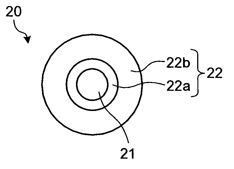
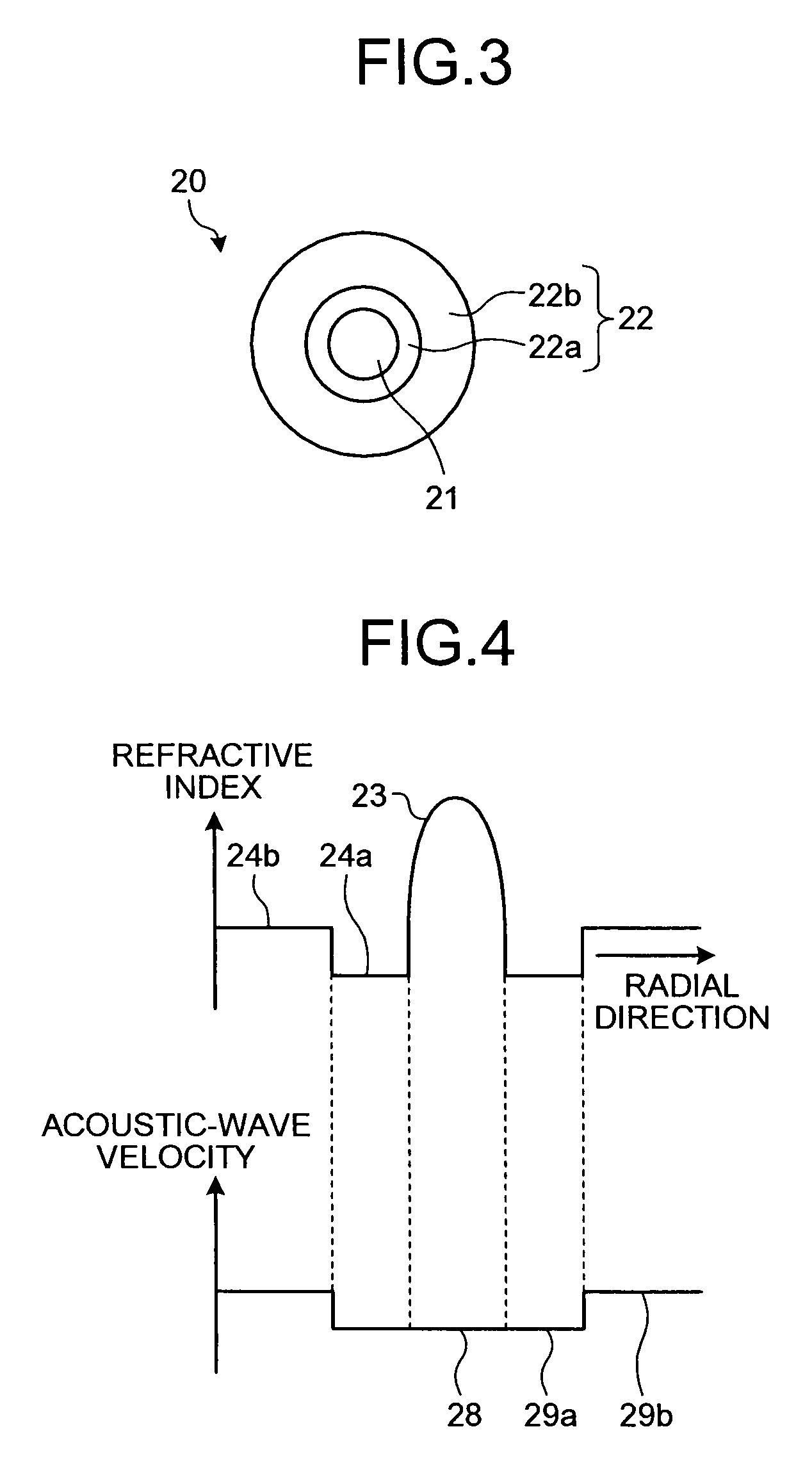
[0032]FIG. 3 is a schematic diagram of an optical fiber 20 according to the present invention. The optical fiber 20 is a silica-based single-mode optical fiber that includes a core 21 and a cladding 22 formed around the core 21. The cladding 22 further includes an inner layer 22a formed around the core 21 and doped with fluorine, and an outer layer 22b formed around the inner layer 22a.

[0033]The core 21 is doped with GeO2 by 22.50 wt % and Al2O3 by 11.82 wt %. The core diameter is 7 μm. The inner layer 22a is doped with fluorine that decreases both the refractive index and the acoustic-wave velocity by 3.50 wt %, and the outer layer 22b is made of pure silica glass. The diameter of the inner layer 22a is 23 μm. The doping amount W1 of GeO2 in wt % into the core 21 is thus larger than 4.74+0.64×3.50, and, when a doping amount W3 of fluorine into the inner layer 22a is 3.50 as described above, the doping amount W2 of Al2O3 in wt % thus satisfies −2.814+0.594×W1−0.380×W3≦W2≦54.100+0.2...


PUM

PropertyMeasurementUnit
Poweraaaaaaaaaa
Wave velocityaaaaaaaaaa
Refractive indexaaaaaaaaaa

Abstract

An optical fiber made of silica-based material includes a core and a cladding formed around the core. The core is doped with germanium dioxide, which increases refractive index and decreases acoustic-wave velocity, and aluminum oxide, which increases both refractive index and acoustic-wave velocity, satisfying −2.814+0.594×W1≦W2≦54.100+0.218×W1, W1+W2≦60, and W2≧56.63−2.04×W1, where W1 is doping amount of germanium dioxide in weight percentage, which is larger than 4.74, and W2 is doping amount of aluminum oxide in weight percentage. A nonlinear coefficient of the optical fiber is equal to or larger than 2.6×10⁻⁹W−1.

Description

BACKGROUND OF THE INVENTION[0001]1. Field of the Invention[0002]The present invention relates to an optical fiber capable of suppressing the stimulated Brillouin scattering.[0003]2. Description of the Related Art[0004]To realize a high-capacity optical communication, communication techniques such as the wavelength division multiplexing (WDM) and the time division multiplexing (TDM) are employed. In such communication techniques, as the intensity of an incident light input to an optical fiber used as a transmission line increases in the optical fiber, nonlinear optical effects increases in the optical fiber. The stimulated Brillouin scattering (SBS), one of the nonlinear optical effects, is a phenomenon that a part of the incident light is scattered backward and that the scattered light, i.e. the Brillouin-scattered light, stimulates further scattering. The SBS is caused by an interaction between the light and an acoustic wave in the optical fiber. The SBS is unfavorable because it d...

Claims


Application Information

Patent Timeline
IPC IPC(8): G02B6/00
CPCC03B2201/12C03B2201/31G02B6/03627C03C13/046G02B6/0281C03B2201/32
Inventor TADAKUMA, MASATERU
Owner FURUKAWA ELECTRIC CO LTD
Why Eureka
Try Eureka