
Articles of peptide nanostructures and method of forming the same

a technology of peptide nanostructures and nanotubes, which is applied in the direction of pretreatment surfaces, electrical appliances, and yarns, etc., can solve the problems of high cost of carbon nanotube production process, inability to meet the requirements of a single particle size,

Inactive Publication Date: 2009-03-05
RAMOT AT TEL AVIV UNIV LTD
View PDF100 Cites 33 Cited by
  • Summary
  • Abstract
  • Description
  • Claims
  • Application Information

AI Technical Summary

Benefits of technology

[0077]Unless otherwise defined, all technical and scientific terms used herein have the same meaning as commonly understood by one of ordinary skill in the art to which this invention belongs. Although methods and materials similar or equivalent to those described herein can be used i...

Problems solved by technology

However, carbon nanotubes in general and carbon-nanotube fibers in particular suffer from structural deviations.
Although deviations in structure can be introduced in a “controlled” manner under specific conditions, frequent uncontrollable insertion of such defects result in spatial structures with unpredictable electronic, molecular and structural properties.
In addition, the production process of carbon nanotubes is very expensive and presently stands hundreds of U.S. dollars per gram.
However, no individual nanotubes could be formed by crystallization, as the crystallization conditions used in this study included evaporation of an aqueous solution at 80° C. No formation of discrete nano-structures was reported under these conditions.

Method used


Image

  • Articles of peptide nanostructures and method of forming the same
  • Articles of peptide nanostructures and method of forming the same
  • Articles of peptide nanostructures and method of forming the same

Examples


example 1

[0172]Thin film of peptide nanostructures was manufactured, in accordance with preferred embodiments of the present invention.

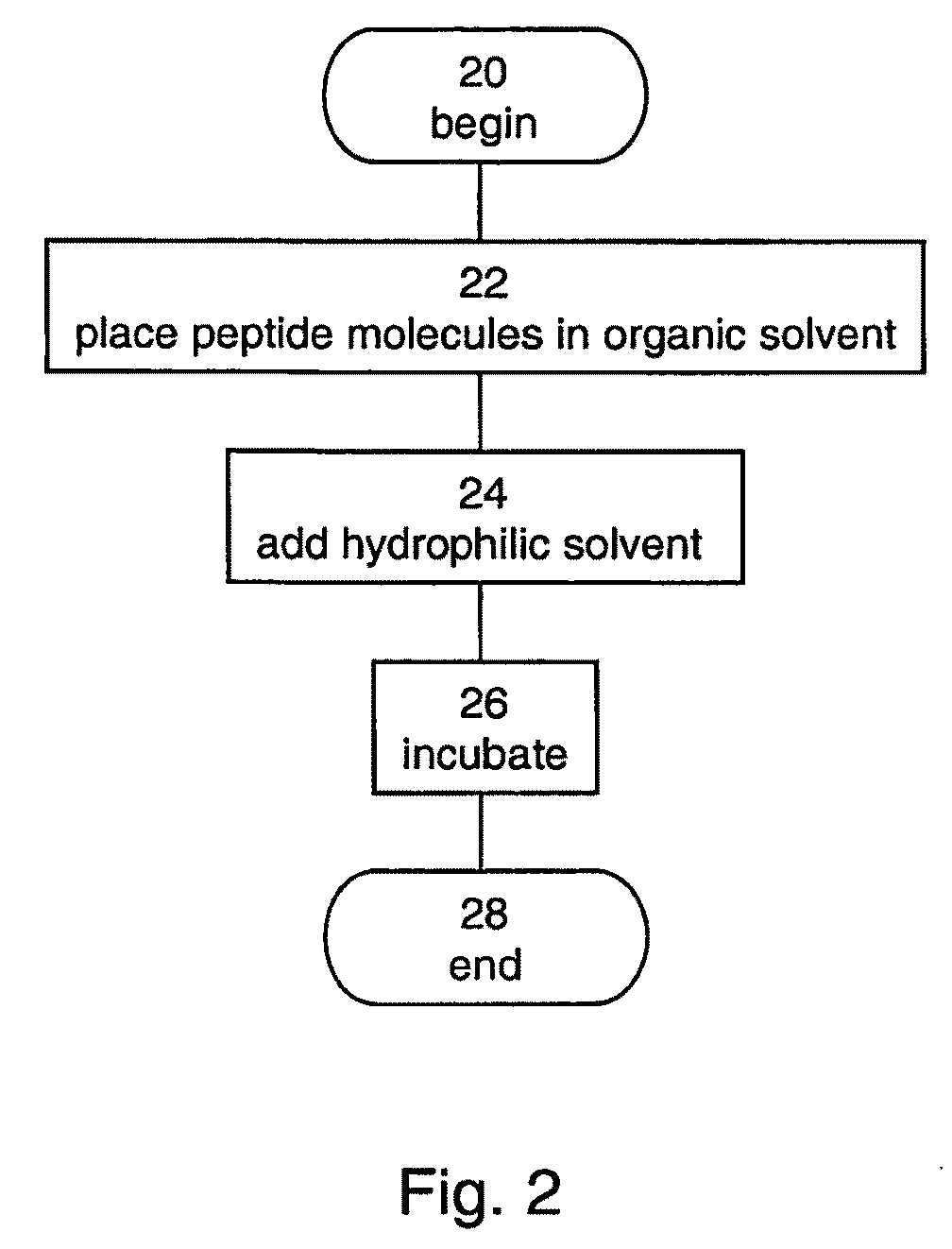
[0173]The manufacturing process is shown in FIGS. 5A-C. In a first step, shown in FIG. 5A, Boc-FF-COOH dipeptide was dissolved in benzene to a concentration of 10 mg / ml and placed in a reaction beaker. In a second step, shown in FIG. 5B, a water solution was added into the reaction beaker. As shown in FIG. 5B, an interface was formed between the benzene and the water solution. The benzene and the water solution were incubated for several hours. FIG. 5C shows a film of Boc-FF-COOH dipeptide which was formed at the interface after incubation.

example 2

[0174]The Langmuir-Blodgett technique was employed to manufacture a thin film of peptide nanostructures, in accordance with preferred embodiments of the present invention.

[0175]A droplet of Boc-FF-COOH dipeptide was dissolved in chloroform-methanol (9:1) to a concentration of 1 mg / ml. The resulted solution was then applied on a surface of water in a Langmuir-Blodgett trough. Moving barriers, positioned at the ends of the trough were used to apply pressure on the droplet, and a film of nanostructures was formed.

[0176]FIG. 6 shows a pressure-area isotherm obtained while applying the pressure. As shown in FIG. 6, the surface tension increases when the surface area is decreased, and peptide molecules are assembled together into a monolayer, which is further compressed into a film.

example 3

[0177]An array of peptide nanostructures was manufactured on a substrate, in accordance with preferred embodiments of the present invention.

[0178]Diphenylalanine peptide was dissolved to a concentration of 100 mg / ml in 1,1,1,3,3,3-Hexafluoropropanol. 30 μl of the solution were applied onto siliconized glass and let to dry in room temperature.

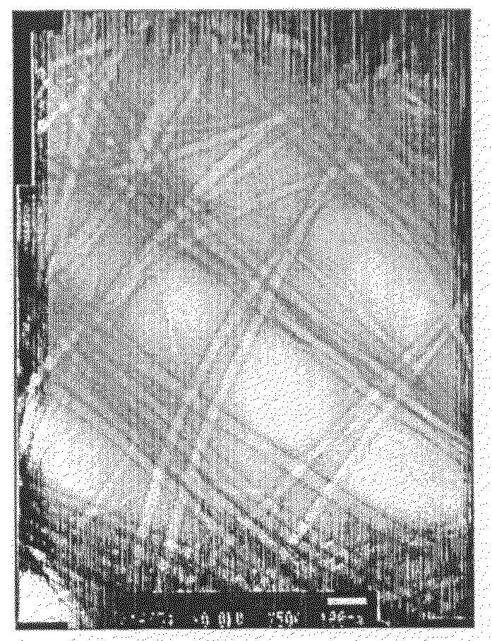
[0179]FIGS. 7A-B are a low magnification (FIG. 7A) and a high magnification (FIG. 7B) images of the substrate, obtained using a high-resolution scanning electron microscope. As shown in FIGS. 7a-b, an aligned array of peptide nanotubes was formed on the substrate.


PUM

PropertyMeasurementUnit
Lengthaaaaaaaaaa
Areaaaaaaaaaaa
Sizeaaaaaaaaaa

Abstract

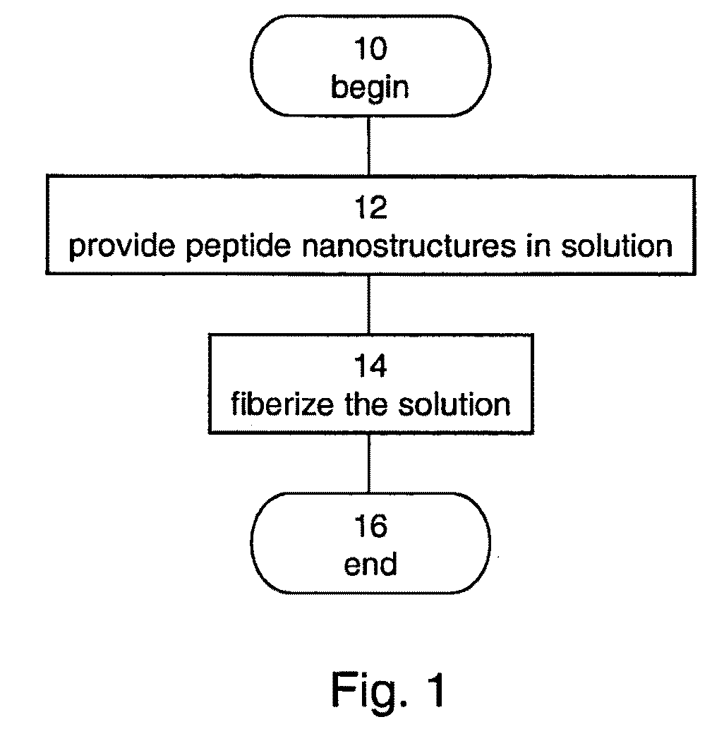
A method of forming a fiber made of peptide nanostructures is disclosed. The method comprises: providing peptide nanostructures in solution, and fiberizing the solution thereby forming at least one fiber of the peptide nanostructures. Also disclosed are methods of forming films and other articles using the peptide nanostructures.

Description

FIELD AND BACKGROUND OF THE INVENTION[0001]The present invention relates to articles made of nanostructures and, more particularly, to articles made of peptide nanostructures having sizes at least in the micrometer scale.[0002]Material sciences involve the understanding of material characteristics as well as the development of new materials. Industrial and academic needs encourage material scientists to develop new materials having superior mechanical, electrical, optical and / or magnetic properties for many applications. Modern material sciences focus on the investigation of polymers, ceramics and semiconductors in many fluidic as well as solid forms including fibers, thin films, material bulks and the like.[0003]Various manufacturing processes are known in the art for making synthetic fibers. Many synthetic fibers are produced by extrusion processes, in which a thick viscous liquid polymer precursor or composition is forced through one or more tiny holes of a spinneret to form cont...

Claims


Application Information

Patent Timeline
IPC IPC(8): B32B5/02B29C47/00C07K1/00D04H13/00B05D3/12
CPCC07K5/06078C07K5/06191C08J5/18C08J2300/16Y10T428/253D01F1/10D01F4/00D01F6/68Y10T428/298D01D5/00Y10T442/60Y10T442/614
Inventor GAZIT, EHUDRECHES, MEITAL
Owner RAMOT AT TEL AVIV UNIV LTD
Learn More