[0021]In further related embodiments to the invention described herein, a funnel guide may be coupled to the case, the array capable of being inserted into the case by passing the array through the funnel guide and an opening of the case. The funnel guide may be removably attached to the case. The funnel guide may include walls defining a slit, the array capable of being passed through the slit. Liquid may be substantially prevented from passing through the slit in the absence of the array due to, for example,
surface energy. The walls defining the slit may be capable of being deformed to allow the array to pass through the slit, and may be made, for example, of plastic. The slit may be capable of being opened and closed. The funnel guide may include brushes for spreading of the at least one of sample and
reagent. The at least one cover of which is light transmissive may be coated with a hydrophilic layer to prevent
fogging. At least one of the frame and the covers may includes a hydrophilic strip for promoting spreading of sample during array loading. At least one of the array and the case may include an identifier, such as a
barcode.
[0035]In accordance with another embodiment of the invention, a method of conducting an assay on a plurality of samples includes performing an assay at each sample site in a sample array having greater than 100 sample sites. Each assay provides an optical effect. Each of the sample sites simultaneously imaged to produce
imaging data pertinent to the optical effect of each site.
[0037]In accordance with another embodiment of the invention, a method of conducting an assay on a plurality of samples includes performing an assay at each of a plurality of sample sites in a sample array, the sample array having a sample site density greater than one sample site per 20 mm2. Each assay provides an optical effect. Each of the sample sites is simultaneously imaged to produce
imaging data pertinent to the optical effect of each site.
[0039]In accordance with another embodiment of the invention, a method of conducting an assay on a plurality of samples includes performing an assay at each of a plurality of sample sites in a sample array. Each assay provides an optical effect. Each sample site is simultaneously illuminated using one or more
colored LEDs. Furthermore, each of the sample sites is simultaneously imaged to produce imaging data pertinent to the optical effect of each site.
[0042]In related embodiments of the invention, the
thermal cycler may be a flat block having at least one thermally controlled surface. The flat block may be a Peltier device. A
heat transfer pad may be positioned between the case and the surface. The
thermal cycler may include a fluid delivery module for delivering a flow of controlled-temperature fluid over the case. The
system may include an illumination source capable of illuminating each of the through-holes simultaneously. The illumination source may include at least one color LCD. The at least one LCD may be filtered by an
excitation filter. A camera may simultaneously image each of the through-holes to provide imaging data. The
system may further include a processor for
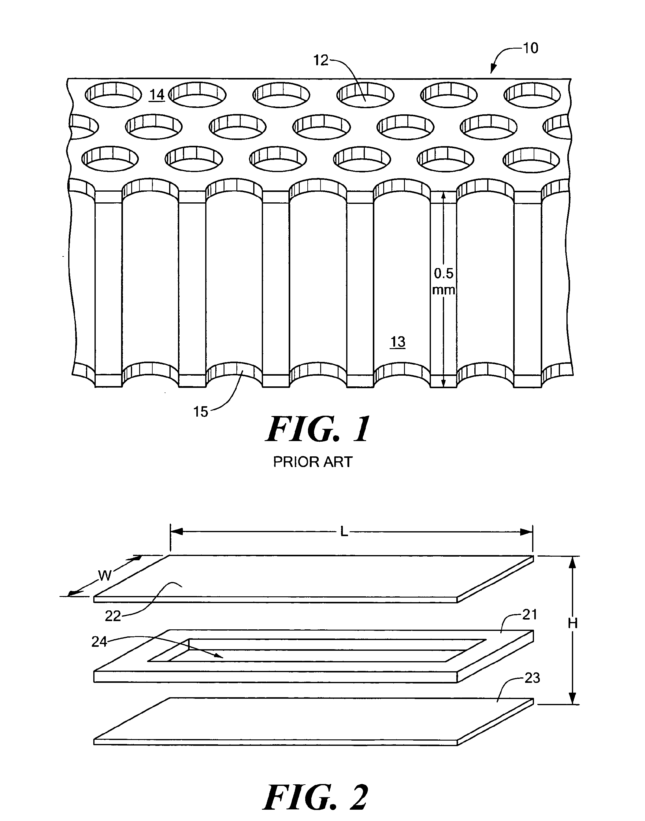
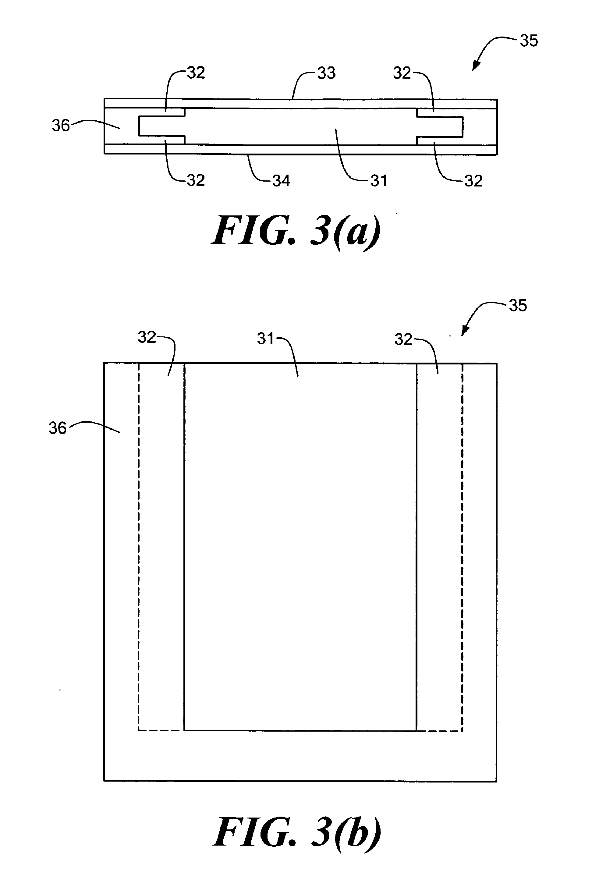
processing the imaging data. The case may include a pair of parallel covers, at least one of which is light transmissive, of which pair a light transmissive cover forms a top, and of which pair the other forms a bottom. A frame disposed between the covers defines, in relation to the covers, an interior volume, the frame and the covers associated with one another to form the case. An encapsulation fluid, which reduces interactions between contents of distinct through-holes, may be disposed in the interior volume.
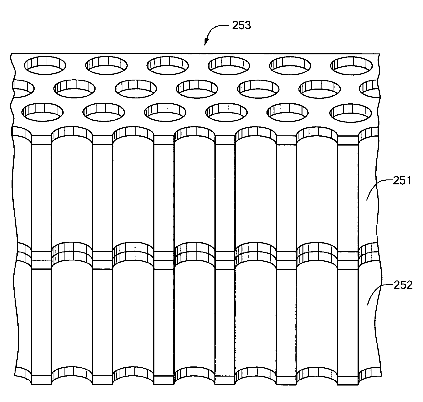
[0046]In related embodiments of the invention, the array may include a hydrophobic surface surrounding the openings of each sample site. The sample sites may include a hydrophilic surface that attracts the at least one of sample and
reagent. The sheet may have a pair of opposed surfaces and a thickness, and the sample sites include a plurality of through-holes running through the thickness between the surfaces. The sample sites may include a plurality of closed-ended wells. At least one cover of which is light transmissive may be coated with a hydrophobic layer to prevent
fogging. The array may include a recessed opening at each sample site, the recess preventing fluid in each sample site from coming into contact with a cover to which each such sample site is
proximate. The
system may further include one of a UV curable sealent and a
grease for sealing the opening. The frame and the covers may be coupled together to form the case by at least one of an
epoxy or other
adhesive. The frame may be, or include, an
adhesive gasket or a compression
gasket. The frame may be puncturable and include includes walls defining a hole, the hole filled with a self-sealing material, which may be, for example, a
grease. The system may further include a funnel guide coupled to the case, the array capable of being inserted into the case by passing the array through the funnel guide and the opening. The funnel guide may be removably attached to the case. The funnel guide may includes walls defining a slit, the array capable of being passed through the slit. Liquid may be substantially prevented from passing through the slit in the absence of the array due to, at least in part,
surface energy. The walls defining the slit may be capable of being deformed to allow the array to pass through the slit. The funnel guide may include brushes for spreading of the at least one of sample and
reagent. At least one of the frame and the covers may include a hydrophilic strip for promoting spreading of sample during array loading.

