Windturbine with slender blade

a technology of slender blades and wind turbines, which is applied in the direction of reaction engines, mechanical equipment, machines/engines, etc., can solve the problems of high wind turbine cost, additional cost, and slender blades, and achieve the effect of reducing spacing, increasing angle, and changing the blades according to invention

Active Publication Date: 2009-03-12
WOBBEN PROPERTIES GMBH
View PDF4 Cites 81 Cited by
  • Summary
  • Abstract
  • Description
  • Claims
  • Application Information

AI Technical Summary

Benefits of technology

[0045]Further advantage of the invention is that the properties of the produced blades according to the invention can be changed by adaptation of the lift enhancing means and in particular the VG-pattern regarding position, type, mutual spacing, size etc. When a further delay of stall is preferred possible VG-pattern adaptations are: Increasing the size of VGs (e.g. 25%), reducing the spacing in between VGs (e.g. 25%), placing more VGs (e.g. an additional basis line), increasing the angle between the flow and VGs (e.g. by 5°), changing the position of the VGs (e.g. 5% c), etc. In particular when the sound emission of a turbine is too high, the tip speed ratio may be reduced. Then adaptation of the blades to more optimal operation at higher angles of attack is preferred. Other cases wherein adaptability is also relevant are when blades of about the same design are used for different wind climates or on different turbines.
[0046]Further advantage is obtained by the application of controllable VGs. This can be used to decrease the maximum lift above rated wind speed, which may be reason to increase the cut out wind speed. It also can be used as a method to decrease the torque of the rotor in case of a failure, emergency stop or manual stop, which lowers the cost of other brake systems. The VGs can be switched to an effective state when a delay of low separation is preferred and to ineffective states when not. According to a preferred embodiment of the invention the VGs are be controlled by piezoelectrics or by MEM tabs and in particular by cylindrical MEM devices or piezoelectrics which enable a direct rotation of the vortex generator over e.g. 15°. The VG can be

Problems solved by technology

Wind turbine costs are high because of the loads which require much material.
A disadvantage of the present wind turbines is that the loads by the wind vary and that this variation leads to additional costs.
An extreme case of a disadvantageous load variation is that wherein a blade bends so much that it hits the tower.
At wind speeds above Vcut-out the turbine has to be stopped to avoid overloading, which reduces production and adds uncertainty to the predicted production.
Another disadvantage is relevant at high wind speeds when turbines are usually halted.
The wind pressure on the blades causes high loads because the required chord of the turbine blades is large.
A further disadvantage is that the loads increase when turbines are operated in the wake of other turbines and need to be placed far apart which costs space

Method used


Image

  • Windturbine with slender blade
  • Windturbine with slender blade
  • Windturbine with slender blade

Examples


Embodiment Construction

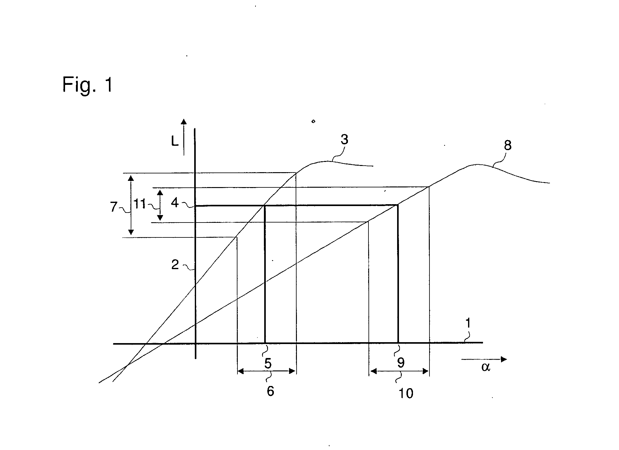
[0057]FIG. 1 shows a plot of the lift L versus the angle of attack α. Curve 3 shows the relation for a classical airfoil without lift enhancing means. To reach a given lift 4 the flow should enter the airfoil under an angle of attack 5. Due to e.g. turbulence in the wind the angle of attack varies in range 6 and therefore the lift will vary in range 7. An airfoil according to the invention with a higher lift coefficient and a shorter chord behaving like curve 8 should reach the same lift 4. This is realised at a larger angle of attack 9. Assuming the same turbulence in the wind, the angle of attack varies in range 10 which is as wide as range 6. Now the surprising element: The lift variation 11 of the airfoil with the higher lift coefficient is less than the lift variation 7 of the classical airfoil.

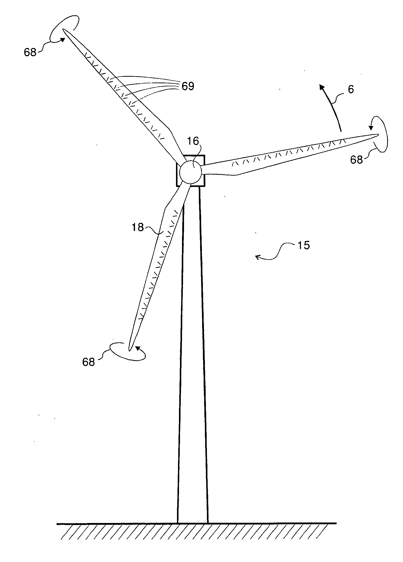
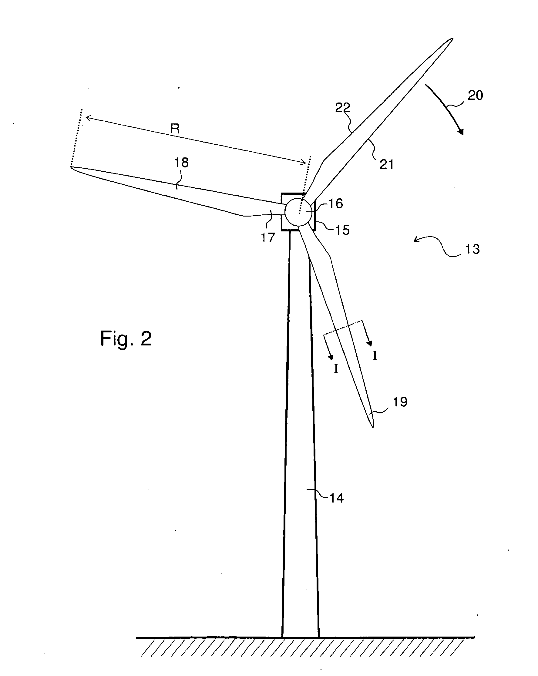
[0058]FIG. 2 shows as example of the invention an upwind turbine 13 with tower 14 and nacelle 15. The turbine rotor of radius R comprises a hub 16 and blades 18 with tip 19 and root 17. ...


PUM


Abstract

Wind turbine with a rotor blade relatively insensitive to turbulence because it is more slender than prior blades and is nevertheless able to generate sufficient lift by virtue of the fact that flow enhancing elements such as vortex generators combat flow separation. The slenderness is defined by the chord numbers C and D of which C is defined as C=Ncrcl2/R2, in which N is the number of blades, cr is the local chord, cl the lift coefficient, r the radial position, λ the tip speed ratio and R the rotor radius. Subsequently, the chord should be less than what follows from the equation C=M in which M=−1.19+9.74Cp−21.01Cp2+17.50Cp3 and Cp is the power coefficient. This wind turbine is subject to about 2-12% less operational loads and to about 5-40% reduced survival wind speed loads compared to classical designs.

Description

FIELD OF THE INVENTION[0001]Wind turbine comprising a rotor with airfoils with a reduced ratio between the variation of the lift force and the average lift force.BACKGROUND OF THE INVENTION[0002]The wind turbine can be a horizontal axis wind turbine or a vertical axis wind turbine comprising a rotor with rotor blades, with N the number of rotor blades and R the blade radius. Due to rotation, the blade tip at radius R obtains a tip speed vtip equal to the product of the rotor speed ω and the rotor radius R: vtip=ωR. The undisturbed wind speed V is the wind speed at the locus of the axis of the rotor when the wind turbine does not disturb the flow. The ratio between the vtip and V is the tip speed ratio λ=ωR / V. An airfoil is a for the aerodynamics optimized profile which is round at the leading edge and sharp or cut off at the trailing edge. One side of the airfoil is the upper side or suction side, the other side is the lower side or the pressure side.[0003]The curve through the cent...

Claims


Application Information

Patent Timeline
IPC IPC(8): F03D1/06F01D5/14
CPCF03D1/0641F03D7/0256Y02E10/723Y02E10/721Y02E10/722F03D11/00F03D1/0633Y02E10/72F05B2240/3062F05B2240/122
Inventor CORTEN, GUSTAVE PAUL
Owner WOBBEN PROPERTIES GMBH
Why Eureka
Try Eureka