Method and device for integrative control of gas engine

a gas engine and integrative control technology, applied in the field of gas engines, can solve the problems of difficult control of air fuel ratio, slow difficult stabilization of engine speed, etc., and achieve the effects of improving the responsiveness to load change, rapid response to load change, and stable speed control

Active Publication Date: 2009-03-19
MITSUBISHI HEAVY IND ENGINE & TURBOCHARGER LTD
View PDF12 Cites 31 Cited by
  • Summary
  • Abstract
  • Description
  • Claims
  • Application Information

AI Technical Summary

Benefits of technology

[0021]The present invention was made in light of problems of prior arts, and the object of the invention is to provide a method and device for integrative control of a gas engine with which load responsivity is improved with accurate air fuel ratio control maintained and further smooth and sophisticated control of engine operation is made possible by uniting air fuel ratio control and speed control so that coordinated control of the engine is performed under cooperation of the speed control and_air fuel ratio control.

Problems solved by technology

However, there has been a disadvantage that response to change of load is slow with the conventional fuel-air mixture control method as mentioned above, although it has an advantage of easiness of controlling air fuel ratio.
There is as one of problems of responsivity a disadvantage that, even if fine control is carried out to stabilize engine speed, stabilization of engine speed is difficult because of slow responsivity.
However, with this conventional method, control of air fuel ratio is difficult, and stable combustion control can not be achieved.
As it is difficult to keep air fuel ratio in an appropriate range, there occurs a problem of compliance with exhaust emission regulation.
Moreover, as fuel flow can not be detected quantitatively with the conventionally prevalent fuel gas flow control method of controlling the opening of the fuel flow control valve, over run or overload of engine due to excessive supply of fuel is apt to occur.
Particularly, engine stall or abnormal combustion is apt to occur at application or rejection of load because of difficulty of accurate control of air fuel ratio when applying or shutting off load.
Furthermore, in the conventional fuel-air mixture control method, it is required to have leeway in supercharging pressure in order to secure ample engine output, and decrease in thermal efficiency is unavoidable due to pumping loss caused by throttling the mixture inlet passage to the main combustion chamber.
On the other hand, with the fuel gas flow control method, the engine is immune from the problem of output shortage due to increased pumping loss, however, it is difficult to keep air fuel ratio in an appropriate range and comply with exhaust emission regulation.
With air fuel ratio control using a signal from the oxygen sensor as a feedback signal as recited in the document 1, manufacturing cost will be increased due to expansive oxygen sensor.
The configuration of the gas engine of the document 1 is suited for a large engine and difficult to adopt for a small engine.
Besides, as a part of air supplied from the compressor is released to outside through the air release valve to control air quantity charged into the combustion chamber, efficiency of the engine is reduced, and a larger compressor is required.
Furthermore, with the conventional control method, air fuel ratio control and engine speed control are performed by separate control devices respectively, however, there is a disadvantage that manufacturing cost increases since the control devices are expensive, and in addition, to assure coordinated behavior of each device is difficult, which makes smooth control of the engine difficult.

Method used


Image

  • Method and device for integrative control of gas engine
  • Method and device for integrative control of gas engine
  • Method and device for integrative control of gas engine

Examples


Embodiment Construction

[0051]A preferred embodiment of the present invention will now be detailed with reference to the accompanying drawings. It is intended, however, that unless particularly specified, dimensions, materials, relative positions and so forth of the constituent parts in the embodiments shall be interpreted as illustrative only not as limitative of the scope of the present invention.

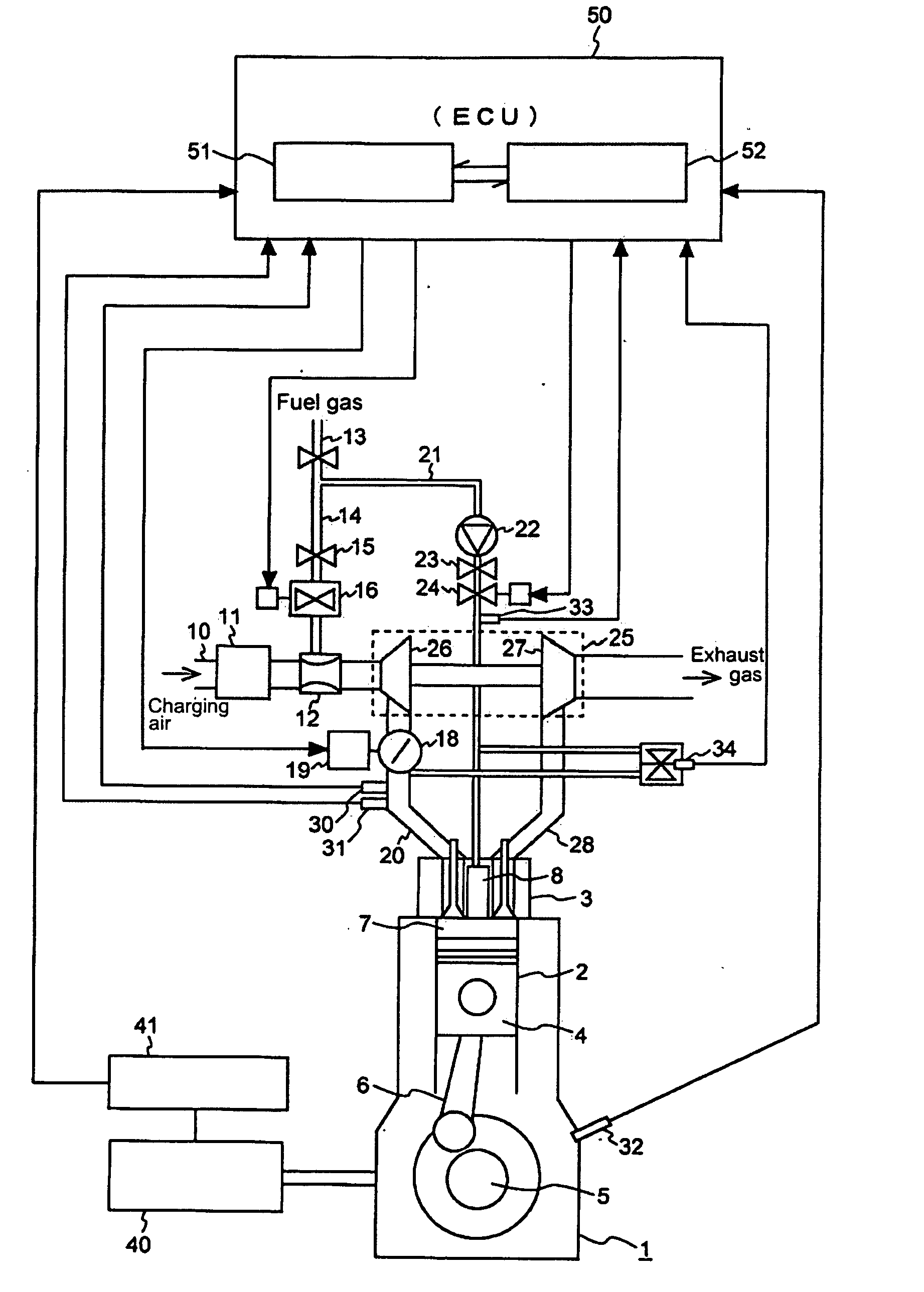
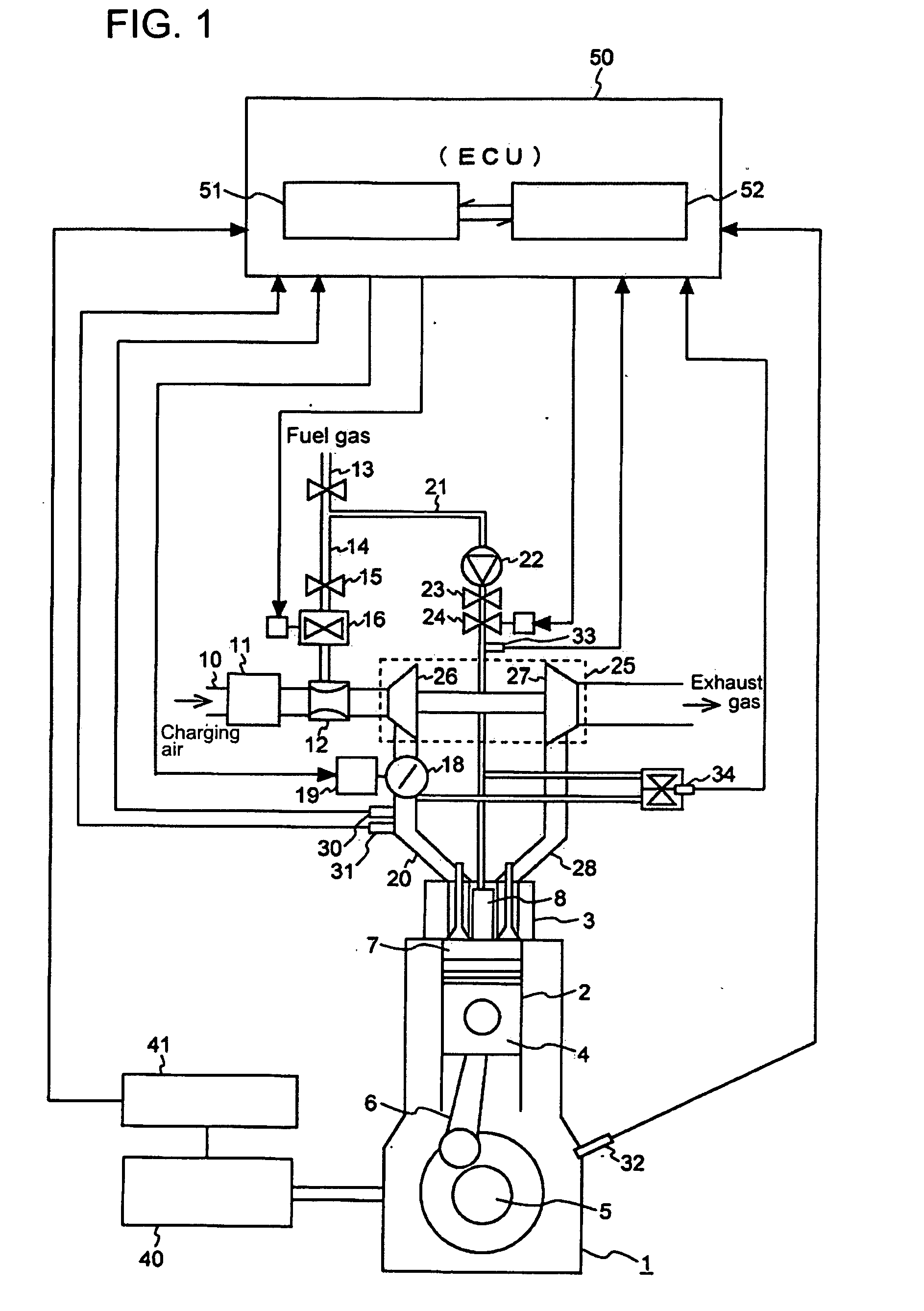
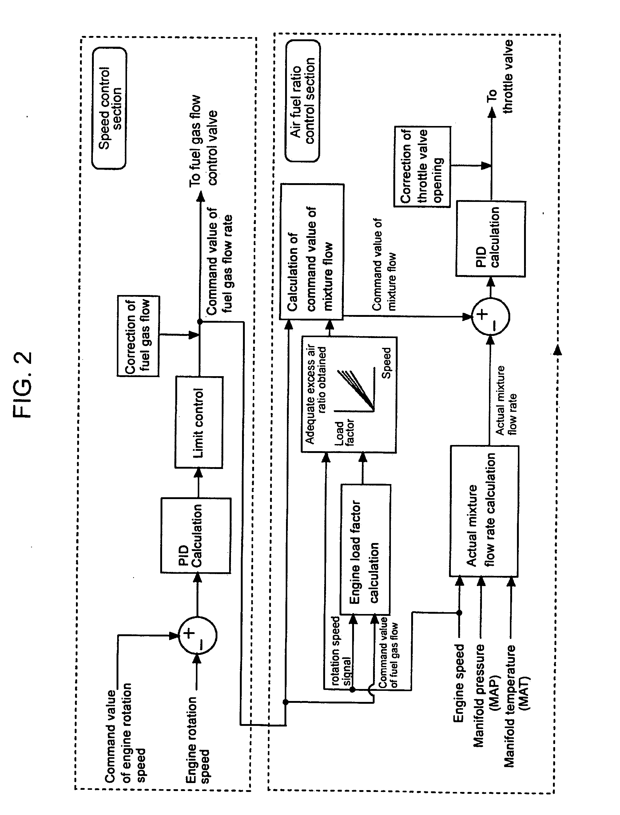
[0052]FIG. 1 is an overall configuration of an embodiment of the control device according to the invention including the gas engine, FIG. 2 is a control block diagram of the gas engine of FIG. 1, FIG. 3 is a table showing an example of limit fuel gas flow map, FIG. 4 is a table showing an example of limit excess air ratio map, and FIG. 5 is a graph for comparing responsivity-to-load, in which FIG. 5A is a case without correction, and FIG. 5B is a case with correction. FIG. 6 is a table showing an example of adequate of excess air ratio map.

[0053]Overall configuration of the gas engine equipped with an embodiment...


PUM


Abstract

An integrative control method and device for controlling gas engines is proposed which is improved load responsivity of the engine while maintaining air fuel ratio control. The control method comprises a speed control process for controlling engine rotation speed by calculating a command value of fuel gas flow rate based on deviation of a detected engine rotation speed from a target command value of engine rotation speed and controlling fuel gas flow rate flowing through the fuel gas flow control valve to coincide with the calculated command value of fuel gas flow rate, and an air fuel ratio control process for controlling air fuel ratio of fuel-air mixture supplied to the combustion chamber of the engine through performing feedback control in which such a command value of fuel-air mixture flow rate is calculated that air fuel ratio of the mixture is appropriate with the fuel gas flow flowing at the commanded fuel gas flow rate and a target opening of the throttle valve is determined based on deviation of the actual mixture flow rate calculated based on detected values of operating conditions of the gas engine from the calculated command value of fuel-air mixture flow rate.

Description

BACKGROUND OF THE INVENTION[0001]1. Field of the Invention[0002]The present invention will be applied to a gas engine in which fuel gas introduced via a fuel supply pipe is mixed with air introduced via a charging air supply pipe and this mixture is supplied via a fuel-air mixture supply pipe to a combustion chamber of the engine. The invention relates to a method and device for performing integrative control of a gas engine equipped with a fuel gas flow control valve to its fuel gas supply pipe to control fuel gas flow and a throttle valve to its fuel-air mixture supply pipe to control fuel-air mixture flow, specifically those of a gas engine equipped with an electronic control unit for performing integrative control of engine rotation speed and air fuel ratio by means of the valves.[0003]2. Description of the Related Art[0004]Gas engines are internal combustion engines which use as fuel gaseous fuel such as natural gas. They can output high driving power with high efficiency, and ...

Claims


Application Information

Patent Timeline
Patent Type & Authority Applications(United States)
IPC IPC(8): F02D9/08F02D41/14
CPCF02B37/00F02B2275/14F02D31/002F02D41/0007F02D41/0027F02D41/187F02D19/027F02M21/047Y02T10/144Y02T10/32F02M21/0236F02M21/0284F02D19/024F02D2200/0406Y02T10/12Y02T10/30
Inventor SHIRAISHI, MASATAKAKAKUHAMA, YOSHITAKASAKAI, KEIKITAMURA, YOSUKE
Owner MITSUBISHI HEAVY IND ENGINE & TURBOCHARGER LTD
Why Eureka
Try Eureka