Fuel Injection Control Apparatus for Internal Combustion Engine

Inactive Publication Date: 2009-03-19
HITACHI LTD
View PDF7 Cites 20 Cited by
  • Summary
  • Abstract
  • Description
  • Claims
  • Application Information

AI Technical Summary

Benefits of technology

[0006]From the standpoint of reducing fuel consumption, there is a growing demand for reducing a minimum fuel volume that can be injected from a fuel injector. For further reduction of fuel consumption, there are also growing calls for performing a fuel cut operation, i.e., not injecting fuel, whenever an engine output is not necessary and for resuming a fuel injection operation following the fuel cut operation. When resuming the fuel injection, it is necessary to inject

Problems solved by technology

Errors in the opening delay therefore have great effects on an accuracy of the fuel injection amount or injection fuel mass.
As a result, the opening delay varies according to the

Method used


Image

  • Fuel Injection Control Apparatus for Internal Combustion Engine
  • Fuel Injection Control Apparatus for Internal Combustion Engine
  • Fuel Injection Control Apparatus for Internal Combustion Engine

Examples


Embodiment Construction

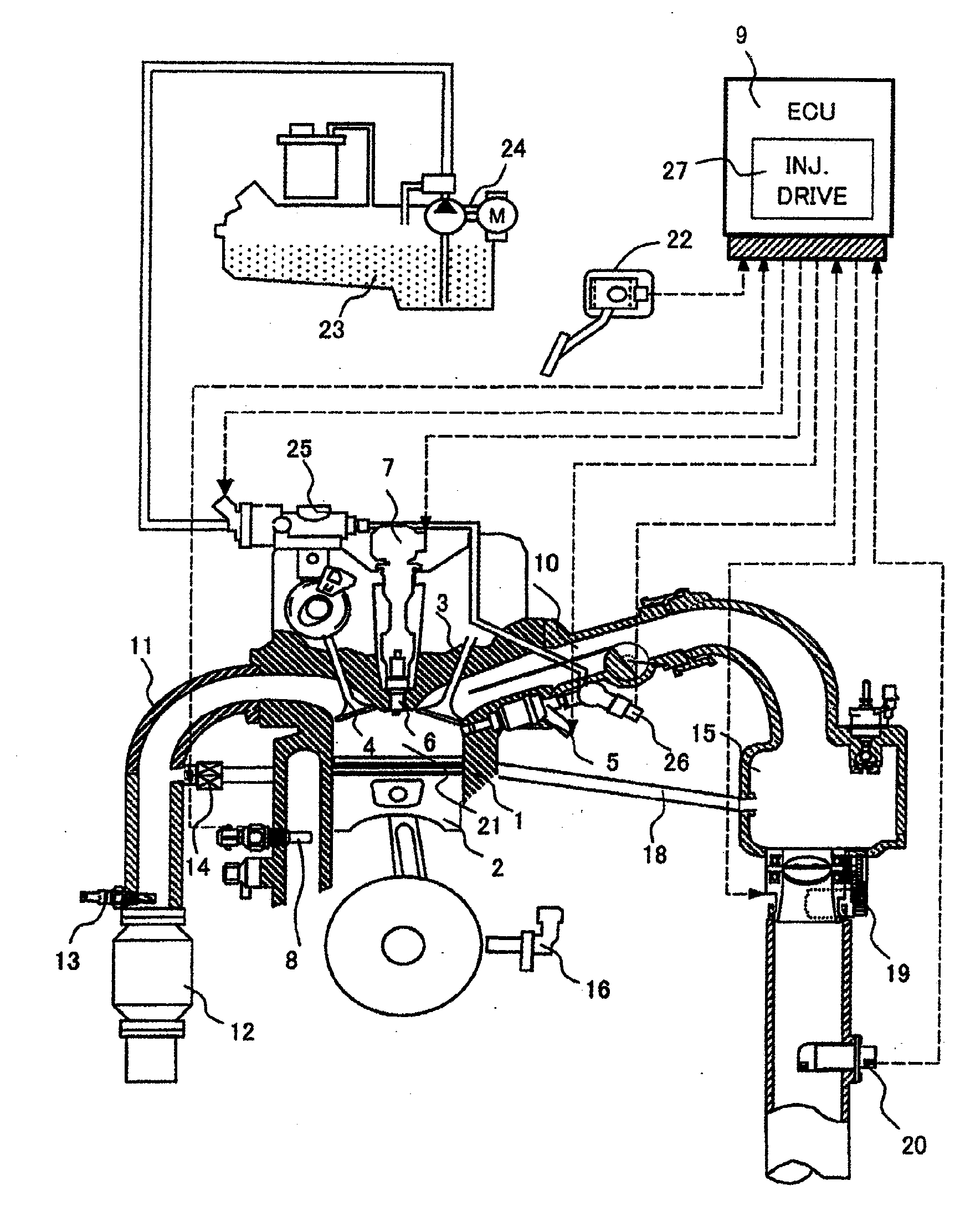
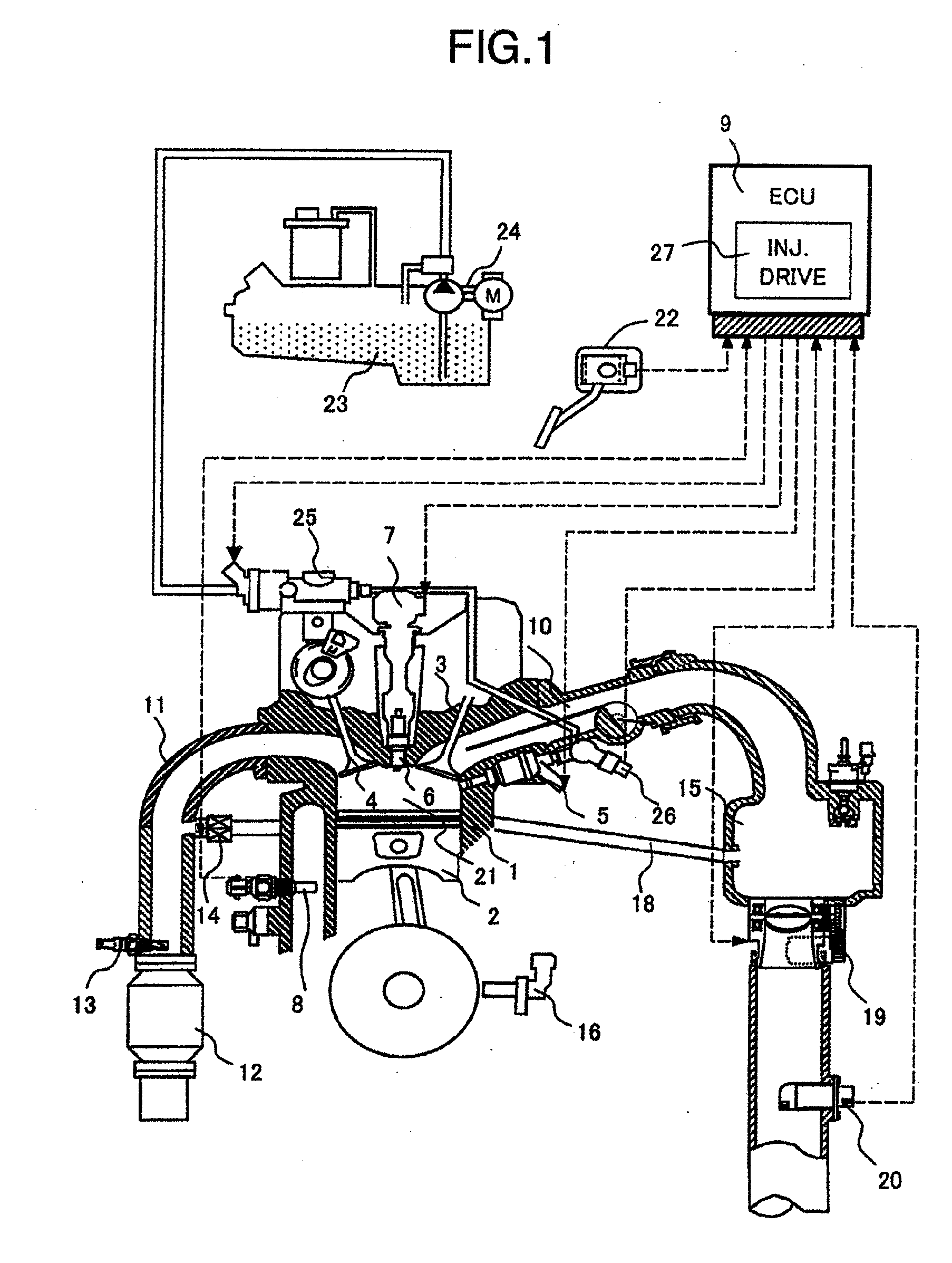
[0051]One embodiment of a fuel injection control apparatus for internal combustion engines according to the present invention will be described by referring to the accompanying drawings. FIG. 1 shows a basic configuration of an internal combustion engine and a fuel injection control apparatus for the engine. In the figure, an engine 1 has a piston 2, an intake valve 3 and an exhaust valve 4. Air drawn in passes through an air flow meter (AFM) 20 and a throttle valve 19 and, from an intake collector 15 or a branch portion, further flows into an intake manifold 10 and the intake valve 3 and into a combustion chamber 21 of the engine 1. A fuel is supplied from a fuel tank 23 by a low-pressure fuel pump 24 into the engine where it is pressurized by a high-pressure fuel pump 25 to a level required for fuel injection. The fuel is injected from a fuel injector 5 into the combustion chamber 21 where it is ignited by an ignition coil 7 and a spark plug 6. A pressure of the fuel is measured b...


PUM


Abstract

A fuel injection control apparatus for an engine including one or more sensors to detect one or more operational states of engine and a fuel state, a fuel injector to activate a plunger rod thereof to inject fuel when an excitation current is supplied to a coil of the fuel injector, and a unit for precharging the coil of the fuel injector with an excitation current smaller than that required to activate the plunger rod of the fuel injector, wherein the current to be precharged to the fuel injector is adjusted according to the one ore more operational states of the engine detected by the one or more sensors.

Description

BACKGROUND OF THE INVENTION[0001]The present invention relates to a fuel injection control apparatus for an internal combustion engine.[0002]The internal combustion engine have a fuel injection control apparatus that calculates an appropriate volume of fuel to be injected according to an operational state of the engine and drives a fuel injector for injecting fuel. The fuel injector opens and closes a plunger rod of the fuel injector to inject fuel by a magnetic force that is generated by an electric current passing through a coil. An amount of fuel to be injected is determined mainly by a difference between a fuel pressure and a peripheral pressure at a nozzle hole of the fuel injector and a time that the plunger rod is kept open to allow the fuel to be injected. Therefore, to inject an appropriate amount of fuel, it is necessary to set the time during which to keep the fuel injector open according to the fuel pressure and at the same time execute the opening and closing operation ...

Claims


Application Information

Patent Timeline
IPC IPC(8): F02M61/16
CPCF02D41/20F02D2200/0602F02D2041/2051F02D2041/2044
Inventor MIYAKE, TAKAOIDE, SHOGO
Owner HITACHI LTD
Why Eureka
Try Eureka