Ventilator

Inactive Publication Date: 2009-03-19
GENERAL ELECTRIC CO
View PDF26 Cites 86 Cited by
  • Summary
  • Abstract
  • Description
  • Claims
  • Application Information

AI Technical Summary

Benefits of technology

[0009]The airflow directing means preferably also includes an inhalation strut assembly and exhalation valve assembly. The inhalation strut assembly may include an area of reduced diameter in the form of an orifice disk to provide a pressure differential on the inlet and outlet sides thereof. The inhalation strut assembly includes at least one pressure sensor positioned to receive input from both an inlet and outlet side of the orifice disk. Additionally, the outlet side of the inhalation strut preferably includes a diffuser to increase the dynamic range of differential pressure for greater sensor sensitivity.
[0010]The exhalation valve assembly has a series of sensors associated therewi

Problems solved by technology

As the filter becomes obstructed with debris, the operation of the ventilator deteriorates and may eventually malfunction.
Furthermore, the flow sensors associated with ventilators can be adversely affected by moisture.
If the exhaled air comes i

Method used


Image

  • Ventilator
  • Ventilator
  • Ventilator

Examples


Example

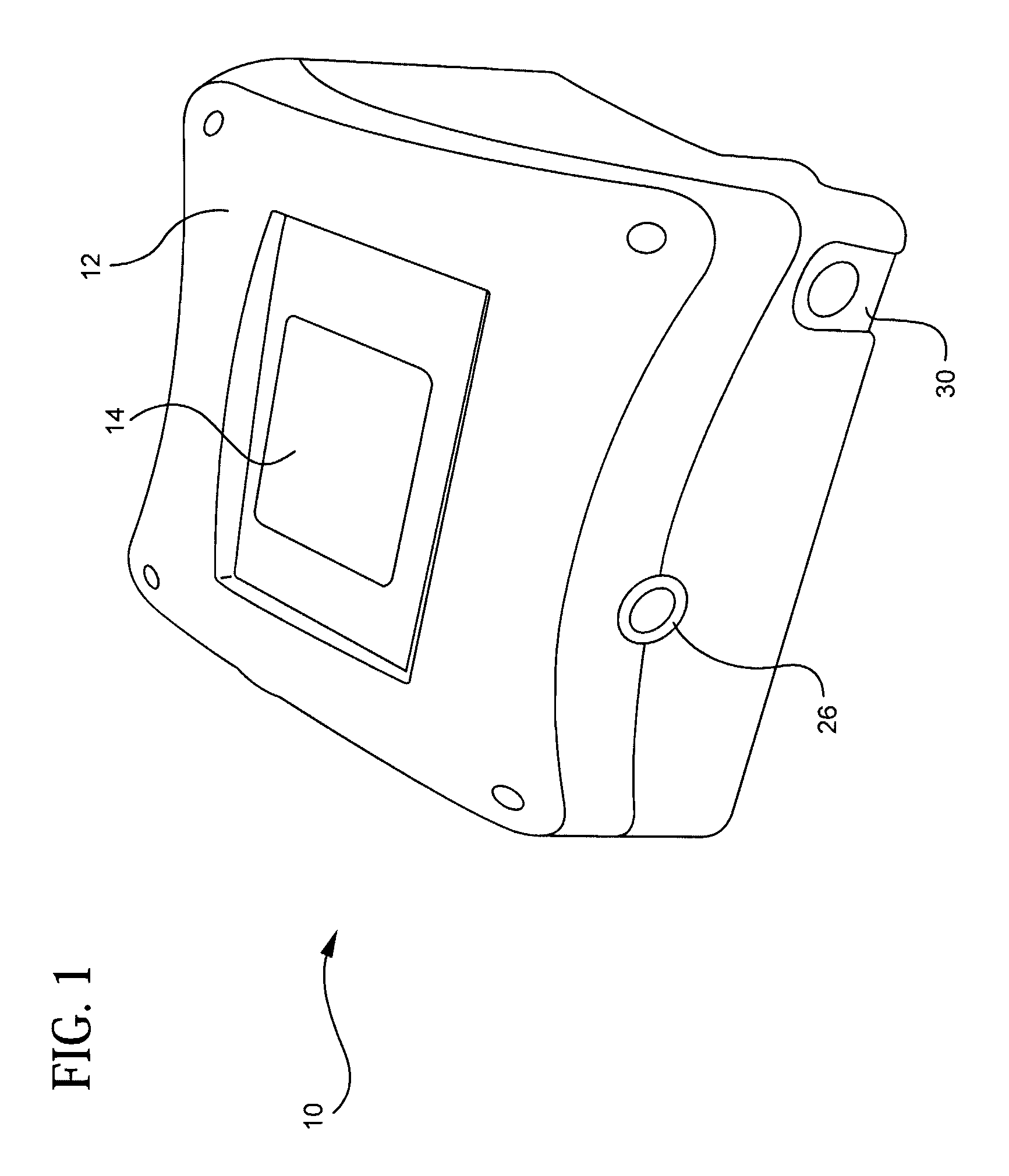
[0025]A medical ventilator formed in accordance with the present invention is illustrated in FIG. 1. The ventilator 10 includes a housing 12 with a touch screen 14 to control the operation of the ventilator, provide patient information, and provide feedback from sensors to monitor a patient's breathing. Also shown in FIG. 1 is the inhalation valve assembly 26 and exhalation valve assembly 30 which, through use of tubing (not shown) to the patient, places the medical ventilator in fluid communication with the patent.

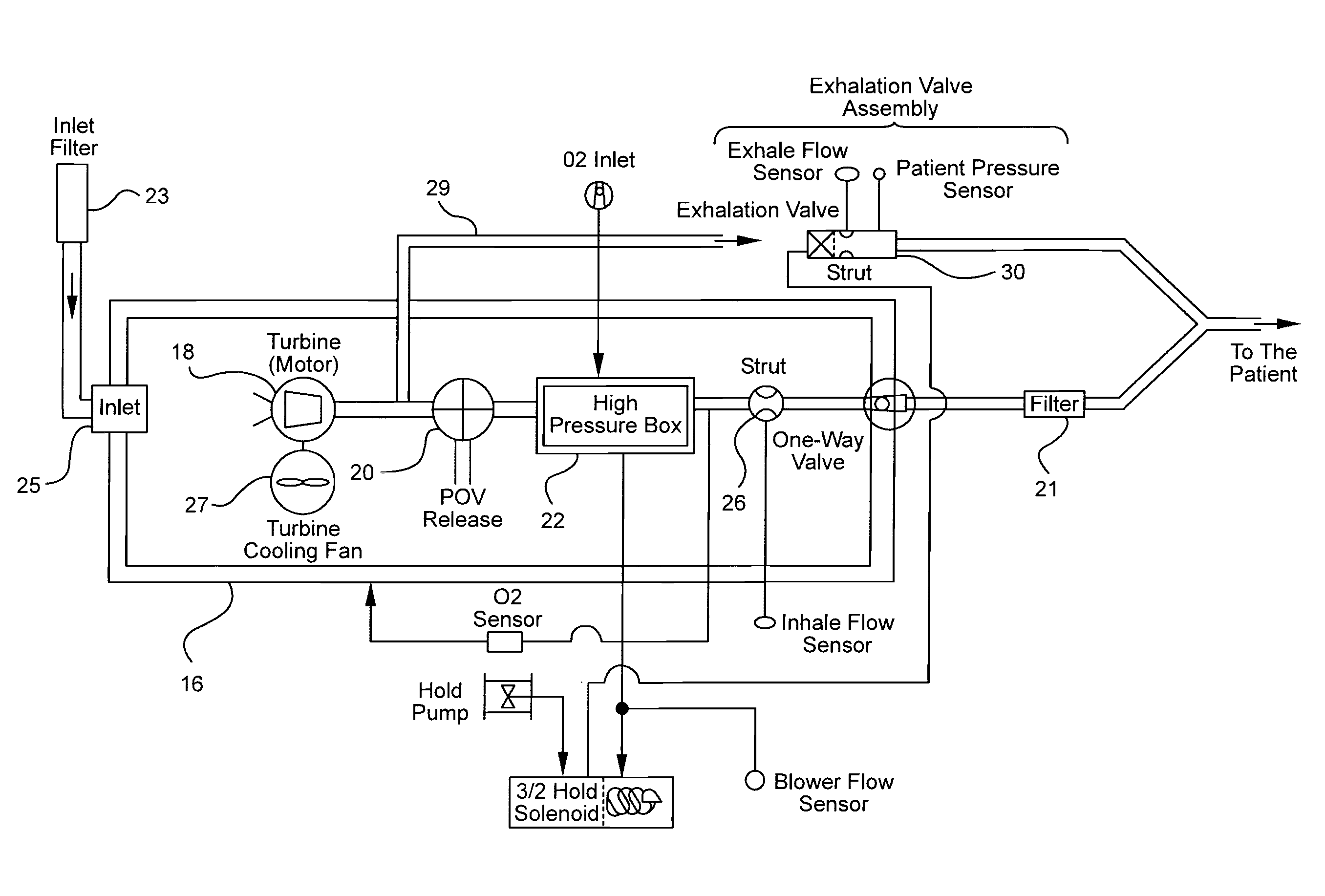
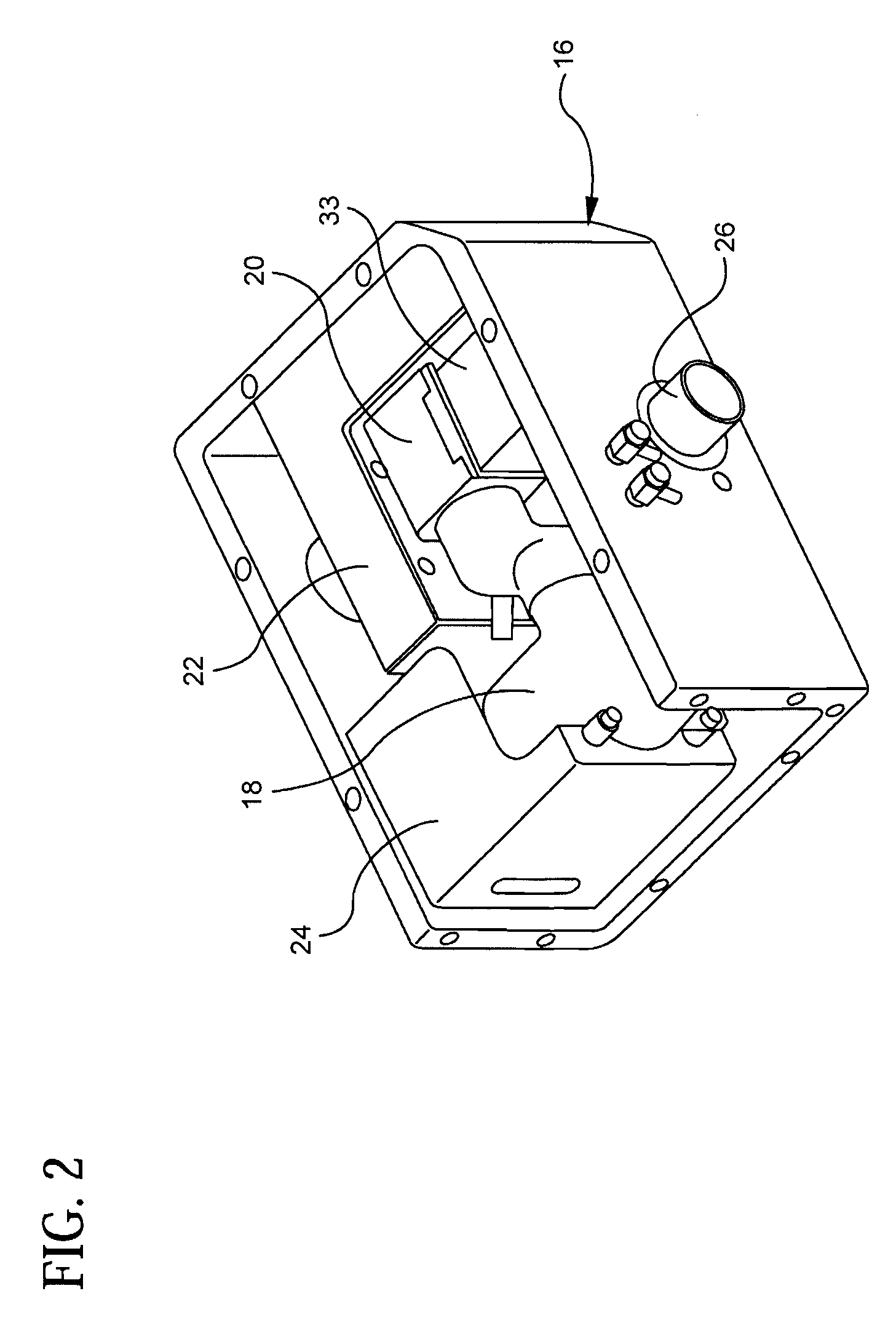
[0026]FIG. 3 is a pneumatic block diagram of the pneumatic components of the ventilator. The major pneumatic components includes a turbine assembly 18 including a turbine and drive motor to create a positive air flow, a control valve to control air flow in the form of a proportional obstacle valve (POV) 20 having a movable valve operated by a stepper motor 33 coupled to the POV, a high pressure box 22, an inhalation valve and strut 26 to provide a one-way path for airflow...


PUM


Abstract

A ventilator to replace or supplement a patient's breathing includes a control valve in the form of a proportional obstacle valve (POV) to provide improved air flow control and ventilator operation reliability. The POV includes an inlet, an outlet and a bypass. A stopcock controlled by a stepper motor directs the flow of air through the bypass and outlet permitting the turbine to operate a constant RPM yet allowing control of the airflow to a patient. The ventilator also includes inhalation and exhalation valve assemblies which improve air flow control and are easy to manufacture. The inhalation valve includes an orifice disk to allow pressure sensors to move accurately measure air flow. The exhalation valve assembly includes wings to reduce turbulence and enhance sensor accuracy. The exhalation valve assembly is arranged to have warm air from cooling the turbine blow over the assembly to reduce the possibility of condensation forming therein. The ventilator also includes an improved power supply with redundant sources of power.

Description

[0001]This application claims the benefit of U.S. Provisional Application Ser. No. 60 / 973,019 filed on Sep. 17, 2007, the disclosure of which is incorporated herein by reference.BACKGROUND OF THE INVENTION[0002]The present invention generally relates to a ventilator for medical use. More particularly, the invention is directed to a medical ventilator having improved airflow control, airflow sensing, increased reliability and a redundant power supply system.[0003]A mechanical ventilator is a machine used to replace or supplement the natural function of breathing. One such device is classified as a positive pressure ventilator, meaning that air is forced out of the ventilator through a drive mechanism such as a piston, turbine, bellows, or high gas pressure. This action raises the pressure in the airways relative to atmospheric pressure, and the resulting increase in intrapulmonary pressure forces the lungs to expand. Thus, ventilators can provide continuous or intermittent mechanical...

Claims


Application Information

Patent Timeline
IPC IPC(8): A61M16/20A62B9/02A61M16/00
CPCA61M16/0051A61M16/204A61M16/06A61M2016/0027A61M2016/0039A61M2016/0042A61M2016/1025A61M2205/16A61M2205/3606A61M2205/505A61M2205/583A61M2205/707A61M2205/8206A61M2205/8262A61M16/107A61M16/0066A61M16/208A61M16/0858A61M16/205A61M16/022G01F1/44
Inventor KALFON, ZIV
Owner GENERAL ELECTRIC CO
Why Eureka
Try Eureka