Method For Controlling A Robot Tool Center Point

a robot tool and center point technology, applied in the field of industrial painting systems, can solve the problems of slow control of paint flow, inability to switch paint on/off synchronously, complex and expensive design of robots to such specifications, etc., and achieve the effect of faster movement of the robot, more uniform coating or paint thickness, and faster painting speed

Inactive Publication Date: 2009-03-19
ABB AS
View PDF4 Cites 27 Cited by
  • Summary
  • Abstract
  • Description
  • Claims
  • Application Information

AI Technical Summary

Benefits of technology

[0018]A prime advantage of the improved method and system for carrying out the method is that painting with an industrial robot may be carried out more quickly. Coverage can be achieved more quickly by providing faster movement of the robot through turns or bends in the paint path. Another technical advantage of the improved method is that by maintaining a constant velocity through the bend a more uniform coating or paint thickness on the surface is achieved.
[0019]Paint wastage is also reduced by means of the improved method which is another very important advantage. Overspray, coating that continues while the applicator is not directly above the surface to be coated, is eliminated. This feature greatly reduces waste of paint, with all the environmental benefits that follow therefrom. Continuous application is maintained, which reduces the necessity for cleaning and flushing the applicator or supply lines, also resulting in reduced paint waste and solvent use.
[0020]Another advantage is that rapid painting may be achieved by use of the described control methods which do not require investment in higher performance robots or robot servo motors for particular joints.

Problems solved by technology

A drawback with the bell applicator is that the control of paint flow is slower, with the result that it is not practical to switch paint on / off synchronously with applicator trajectory.
It is complex and expensive to design a robot to such specifications including for example very high acceleration capabilities.

Method used


Image

  • Method For Controlling A Robot Tool Center Point
  • Method For Controlling A Robot Tool Center Point
  • Method For Controlling A Robot Tool Center Point

Examples


Embodiment Construction

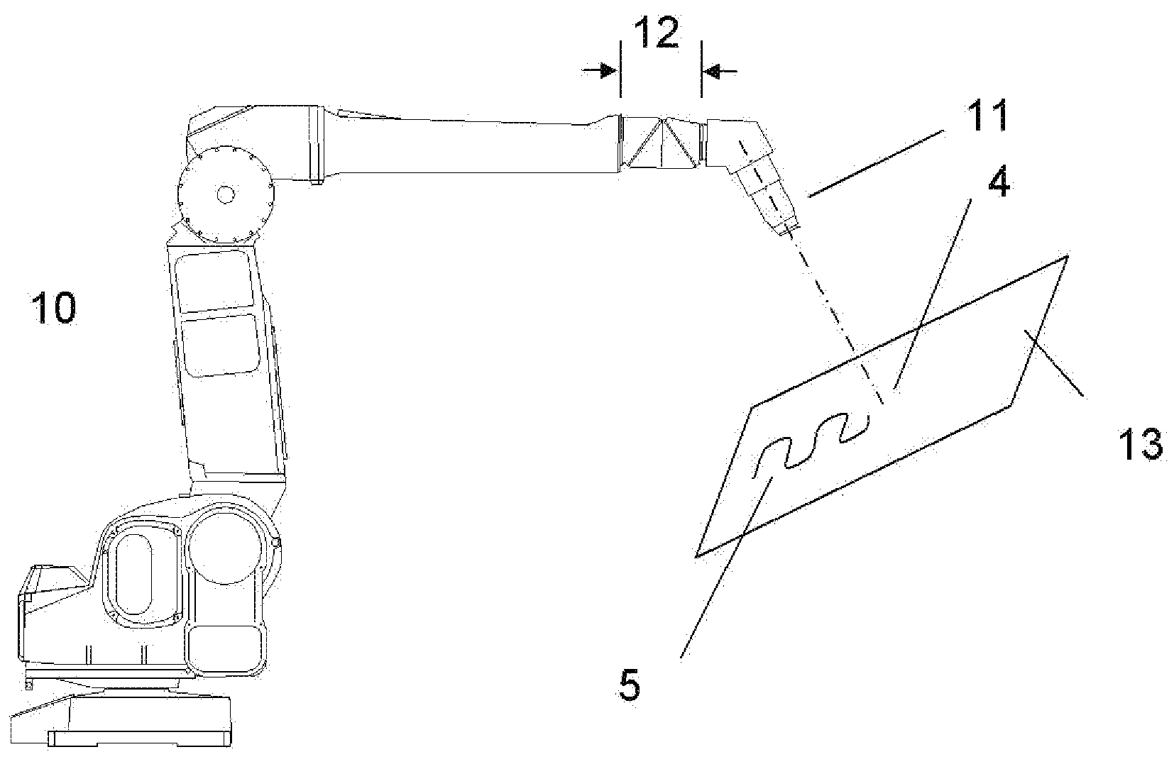
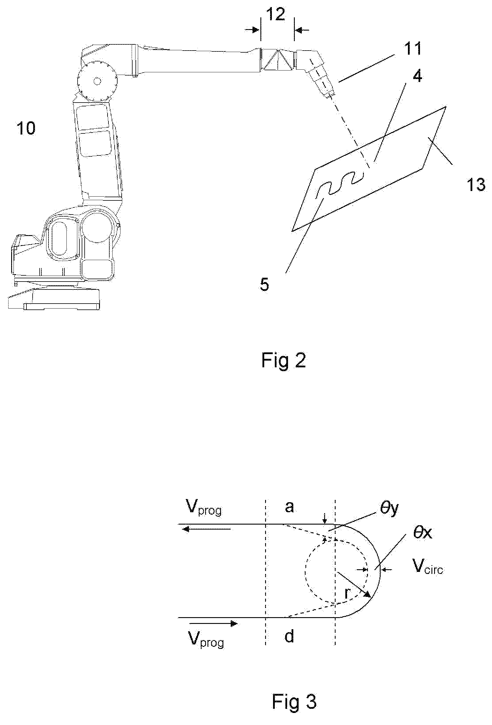
[0031]FIG. 2 shows schematically an industrial robot carrying a paint applicator. The figure shows a robot 10 with an arm carrying a paint applicator 11. The paint applicator is attached to a wrist part 12 arranged on the robot arm. The figure also shows an object with a surface 13 which is to be painted. A planned paint path 5 is indicated on the surface of the object. A center line of the applicator drawn between the applicator 11 and the surface to be painted intersects with the surface at a point, and this point is called the Tool Center Point 4.

[0032]The robot moves the arm and the wrist and orients (points) the applicator 11 so that the tool center point follows the pre-programmed path 5 on the object surface. In this diagram the paint applicator is shown at an angle which is approximately perpendicular to the plane of the paint surface. In other words, the orientation of the paint applicator is perpendicular relative the surface to be painted. Normally a fixed point on the wr...


PUM

PropertyMeasurementUnit
velocityaaaaaaaaaa
angular velocityaaaaaaaaaa
angular accelerationaaaaaaaaaa

Abstract

A method for controlling a painting system including an industrial robot or manipulator arm arranged with a wrist section and carrying a paint applicator arranged on the robot wrist is described. Paint is applied by the applicator to a substantially circular or elliptical area on the surface, the center of the area being defined as a Tool Center Point. The wrist section is arranged capable of moving and orienting the paint applicator. In the method, the paint applicator is moved by the manipulator arm so that the Tool Center Point moves along a planned path so coating a part of the surface. The planned path may include one or more bends. The path taken by the robot wrist may be controlled to follow a different path from the path taken by the Tool Center Point. A system and a computer program for carrying out the method are also described.

Description

CROSS-REFERENCE TO RELATED APPLICATIONS[0001]The present application is a continuation of pending International patent application PCT / IB2007 / 051876 filed on May 16, 2007 which designates the United States and claims priority from European patent application EP 06010330.6 filed on May 19, 2006, the content of which is incorporated herein by reference.FIELD OF THE INVENTION[0002]The invention concerns industrial painting systems, such as automated systems for painting automobiles. In particular it concerns a method for controlling a paint applicator while applying paint in an automated painting process and a system for carrying out that method.BACKGROUND OF THE INVENTION[0003]Industrial robots with an arm or manipulator are often used to paint objects such as automobiles in industrial painting processes. When painting an object surface using a robot or manipulator arm it is desirable to move an applicator over the surface to be painted with a constant velocity in order to ensure good...

Claims


Application Information

Patent Timeline
Patent Type & Authority Applications(United States)
IPC IPC(8): B05D1/02G05B19/04B25J9/02B25J17/02B25J19/00
CPCG05B19/404G05B2219/39363G05B2219/49193G05B2219/45065G05B2219/40545
Inventor KROGEDAL, ARNULFTJOLSEN, JAN INGE
Owner ABB AS
Why Eureka
Try Eureka