Heat Shield Arrangement for a Component Guiding a Hot Gas in Particular for a Combustion Chamber in a Gas Turbine

Inactive Publication Date: 2009-03-26
SIEMENS ENERGY GLOBAL GMBH & CO KG
View PDF17 Cites 42 Cited by
  • Summary
  • Abstract
  • Description
  • Claims
  • Application Information

AI Technical Summary

Benefits of technology

[0016]To prevent residual coolant leaks from the internal space, a sealing element is preferably fitted between the side wall and the supporting structure. By inclining the side wall in the direction of the supporting structure, if the heat shield is fixed to the supporting structure in a detachable manner, a gap can be provided for thermomechanical reasons, which can result in unwanted coolant leaks. It is therefore particularly advantageous to seal off those gaps, which may cause an uncontrolled blowing out of coolant from the internal space, using suitable sealing measures. This provides a leak-tight connection between the heat shield element and the supporting structure. The sealing element between the side wall and the supporting structure is thereby a par

Problems solved by technology

The uncontrolled blowing out of the cooling air however means that more cooling air is used to seal the gaps than is required for the cooling task.
This increase in quantity leads to

Method used


Image

  • Heat Shield Arrangement for a Component Guiding a Hot Gas in Particular for a Combustion Chamber in a Gas Turbine
  • Heat Shield Arrangement for a Component Guiding a Hot Gas in Particular for a Combustion Chamber in a Gas Turbine
  • Heat Shield Arrangement for a Component Guiding a Hot Gas in Particular for a Combustion Chamber in a Gas Turbine

Examples


Example

[0027]The same reference characters have the same significance in the individual figures.

DETAILED DESCRIPTION OF THE INVENTION

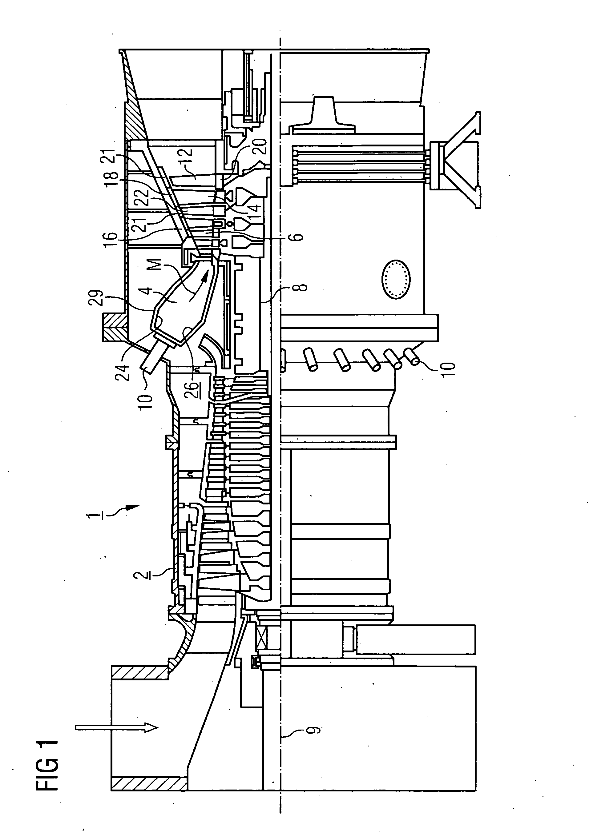
[0028]The gas turbine 1 according to FIG. 1 has a compressor 2 for the combustion air, a combustion chamber 4 and a turbine 6 to drive a compressor 2 and a generator or machine (not shown in further detail here). To this end the turbine 6 and compressor 2 are disposed on a common turbine shaft 8 also referred to as a turbine rotor, to which the generator or machine is also connected, and which is supported such that it can be rotated about its central axis 9. The combustion chamber 4 configured in the manner of an annular combustion chamber is fitted with a number of burners 10 to burn a fluid or gaseous fuel.

[0029]The turbine 6 has a number of rotating blades 12 connected to the turbine shaft 8. The blades 12 are disposed in a rim shape on the turbine shaft 8, thereby forming a number of rows of blades. The turbine 6 also has a number of fixed vanes 14, whic...


PUM


Abstract

The invention relates to a heat shield arrangement for a hot gas (m)-guiding component, which comprises a number of heat shield elements arranged side-by-side on a supporting structure while leaving a gap there between. A heat shield element can be mounted on the supporting structure whereby forming an interior space which is delimited in areas by a hot gas wall to be cooled, with an inlet channel for admitting a coolant into the interior space. According to the invention, a coolant discharge channel is provided for the controlled discharge of coolant from the interior space and, from the interior space, leads into the gap. Coolant can be saved and efficiently used by the specific coolant discharge via the coolant discharge channel, and reduction in pollutant emissions can also be achieved. The heat shield arrangement is particularly suited for linking a combustion chamber of a gas turbine.

Description

FIELD OF THE INVENTION[0001]The invention relates to a heat shield arrangement for a component guiding a hot gas, which comprises a number of heat shield elements disposed next to each other on a supporting structure with gaps in between. A heat shield element can be mounted on the supporting structure such that an internal space is formed, which is delimited in areas by a hot gas wall to be cooled, with an inlet channel for admitting a coolant into the internal space. The invention also relates to a combustion chamber with an internal combustion chamber lining, which has such a heat shield arrangement, and a gas turbine with such a combustion chamber.BACKGROUND OF THE INVENTION[0002]The high temperatures in hot gas channels and other hot gas spaces mean that it is necessary for the internal wall of a hot gas channel to be configured with the highest level of temperature-resistance possible. Materials with a high level of heat resistance, such as ceramic materials, are suitable for ...

Claims


Application Information

Patent Timeline
IPC IPC(8): F23M5/08F23R3/00F23M5/00F23M5/02
CPCF23M5/02F23R2900/00012F23R3/002F23M5/085
Inventor DAHLKE, STEFANPUTZ, HEINRICH
Owner SIEMENS ENERGY GLOBAL GMBH & CO KG
Why Eureka
Try Eureka