Advance instrumentation methods for pipes and conduits transporting cryogenic materials

a technology of cryogenic materials and instrumentation methods, which is applied in the direction of liquid handling, container discharging methods, packaging goods, etc., can solve the problems of short-distance loading and offloading hoses, limited insulation, and high operating and maintenance costs of such systems

Active Publication Date: 2009-03-26
ASTRO TECH GRP LLC
View PDF12 Cites 19 Cited by
  • Summary
  • Abstract
  • Description
  • Claims
  • Application Information

AI Technical Summary

Benefits of technology

[0024]It is generally preferred that two bulkheads cooperate to seal the annular space between the bulkheads. In this configuration, it is typically preferred that the annular space is kept at ambient pressure. However, there may be an advantage

Problems solved by technology

Although such terminals exist—they have been widely used for loading of crude oil and oil products for many years—no offshore terminals for LNG are in use.
The former is limited to short-distance loading and offloading hoses because of the high expense and the limitation of insulation that can be provided.
While low pressure or vacuum systems often provide relatively good insulation, operation and maintenance of such systems tends to be costly, and frequently becomes problematic where such pipelines are submerged on, or even below the sea bed.
Other difficulties are also often encountered, most typically associated with thermal expansion/contraction due

Method used


Image

  • Advance instrumentation methods for pipes and conduits transporting cryogenic materials
  • Advance instrumentation methods for pipes and conduits transporting cryogenic materials
  • Advance instrumentation methods for pipes and conduits transporting cryogenic materials

Examples


Embodiment Construction

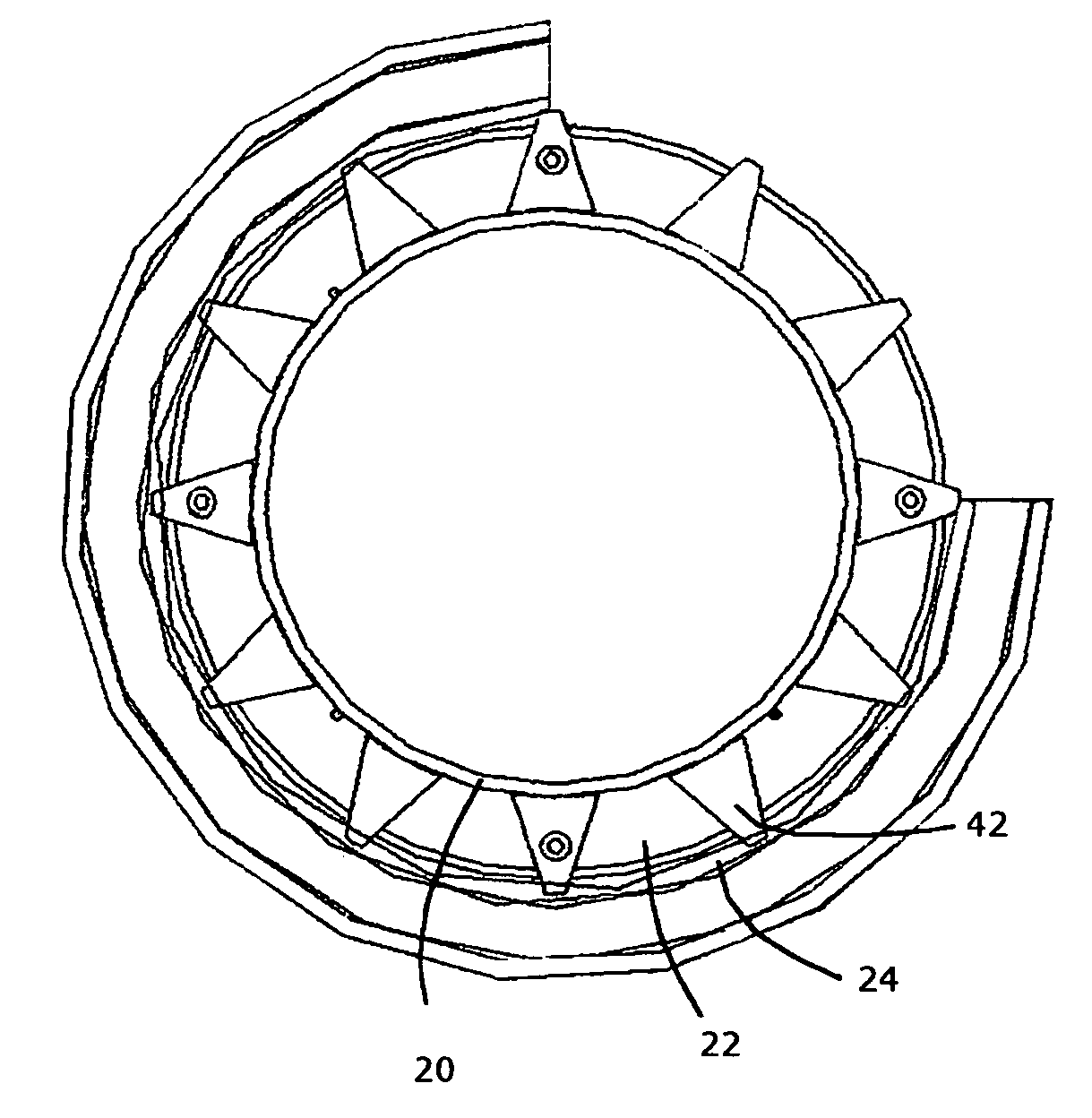
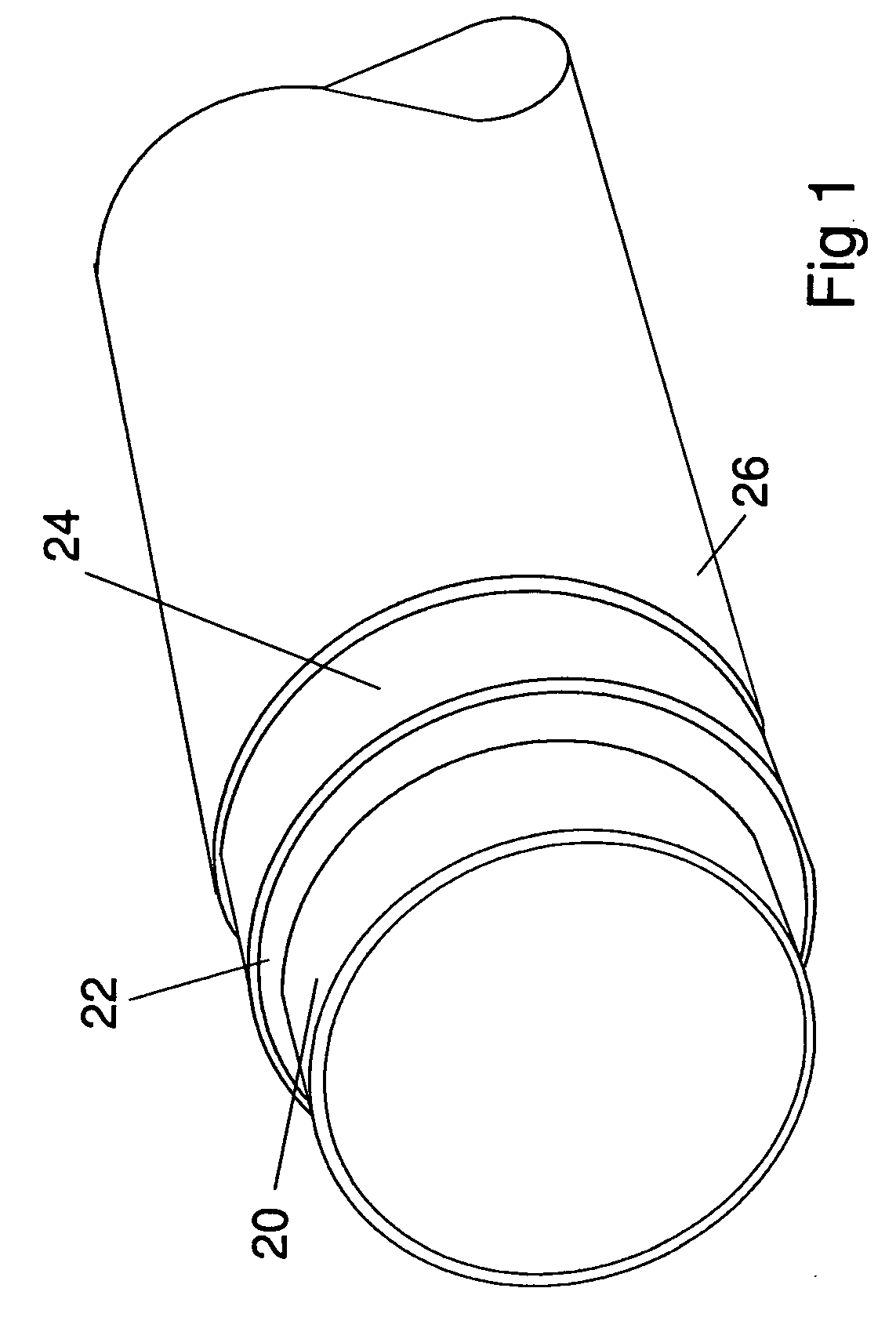
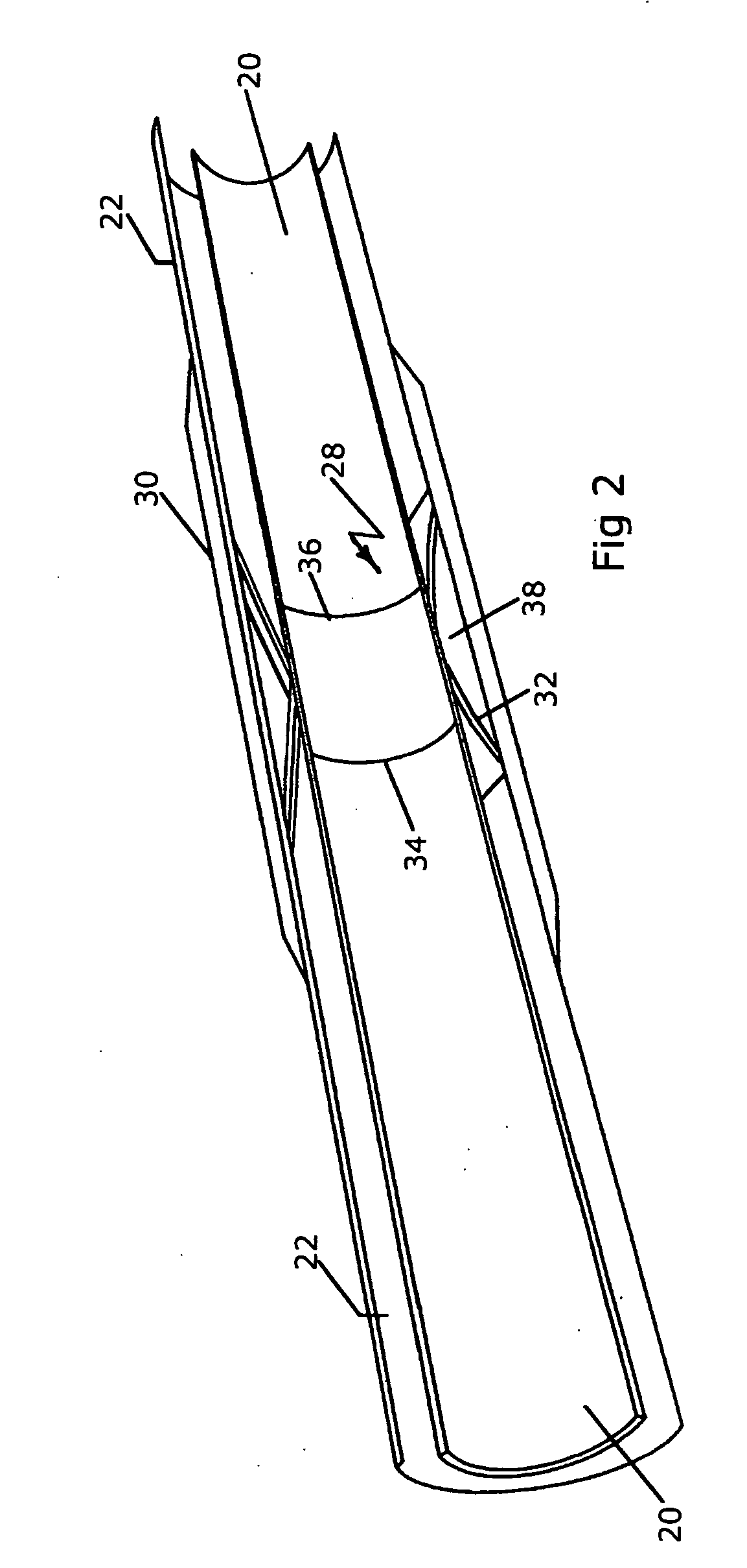
[0034]The subject pipeline technology uses a highly efficient thermal nanoporous insulation in the annular space between the inner and outer pipes and this material is generally kept in an ambient pressure environment as a result of the space being sealed by bulkheads so this environment is maintained. Where leak detection is employed, the pressure will be slightly above ambient pressure. As shown in FIG. 1, the internal cryogenic product pipe for LNG vapor or LPG service is a rigid pipe such as, by way of example the ASTM 333 Grade 8, 9% nickel steel pipe 20. This is surrounded by a nanoporous insulation material 22 which fill the space between the external casing pipe 24, which may be a carbon steel pipe with FBE corrosion coating, and the internal pipe 20. The insulation is typically a flexible aerogel. There is no need for a water stop commonly required in common insulation systems, as the aerogel insulation is contained within a Tyvek™ or similar outer wrapping and the aerogel ...


PUM


Abstract

A cryogenic material transfer system incorporates a pipe-in-pipe configuration with a nanoporous or microporous insulating layer filling the annulus between the inner and outer pipe. The insulating layer is of sufficient flexibility to absorb and expansion or contraction of the inner pipe due to the flow of cryogenic material therethrough. For longer transfer systems a bulkhead is provided between adjacent pipe joints. Intermediately of the pipe joints an additional bulkhead may be employed to provide additional sealing or water stops and for providing provide additional load transfer. A fiber optic sensor system is installed in the annuals between the inner and outer pipe.

Description

CROSS REFERENCE TO RELATED APPLICATION[0001]This application is based on and claims priority under U.S. Provisional Application No. 60 / 914,756, which was filed by David V. Brower, the inventor of the subject invention, on Apr. 29, 2007, and which is incorporated herein by reference.BACKGROUND OF THE INVENTION[0002]1. Field of the Invention[0003]The invention is generally related to instrumentation methods for monitoring and measuring fatigue in pipes or conduits for carrying cryogenic materials and is specifically directed to a pipeline system including fiber optic sensor instrumentation systems and methods.[0004]2. Discussion of the Prior Art[0005]Pipeline transfer of cryogenic fuels and other liquids such as liquid natural gas (LNG) is commonplace throughout the world. In fact, LNG is currently the fastest growing hydrocarbon fuel in the world. While gas as a primary fuel source is forecast to grow at 3% in the coming two decades, LNG is forecast to grow at double that rate over t...

Claims


Application Information

Patent Timeline
IPC IPC(8): F17C6/00F17C9/00
CPCF16L59/141
Inventor BROWER, DAVID V.
Owner ASTRO TECH GRP LLC
Why Eureka
Try Eureka