Switchable rocker arm

a rocker arm and switch technology, which is applied in the direction of valve arrangements, mechanical equipment, machines/engines, etc., can solve the problems of inability to increase tolerances for minor diameter sizes, increase manufacturing costs, and increase the risk of locking pin head jamming in the bore, so as to reduce the net volume of oil displaced and reduce the required return spring force

Inactive Publication Date: 2009-03-26
DELPHI TECH INC
View PDF2 Cites 13 Cited by
  • Summary
  • Abstract
  • Description
  • Claims
  • Application Information

AI Technical Summary

Benefits of technology

[0013]Briefly described, a rocker arm body includes a first and a second oil passage connecting a lock pin bore with a variable oil pressure source, such as a socket for a hydraulic lash adjuster (HLA). The first oil passage leads from the HLA socket to a hydraulic chamber formed by a lock pin head and a retention plug sealing the lock pin bore. The second oil passage leads from the HLA socket to a return spring cavity. Adding the second oil passage will not increase the number of machining operations compared to the known prior art, since at the same time a venting hole typically machined into the follower body can be eliminated. Therefore, oil flow between the HLA and the return spring cavity and between the HLA and the hydraulic chamber above the lock pin head is enabled. Furthermore, leakage between the lock pin head and the wall of the lock pin head is advantageous rather than detrimental as in prior art. Due to the oil circuit in accordance with the invention, the minor diameter of the lock pin, which may be the diameter of the lock pin shaft, now determines the hydraulic force generated by oil pressure and the net volume of oil displaced by the lock pin motion. Compared to prior art lock pin mechanisms, up to 40% less oil needs to be displaced as the pin translates between the extended and retracted positions. Consequently, the viscous flow losses are reduced and switching response is improved, especially with cold oil. Since a smaller hydraulic force is needed to move the lock pin compared to prior art oil circulation, the required return spring force for equivalent switch pressure is reduced compared to prior art, which enables a superior return spring design, such as having a lower rate and / or shorter length.
[0014]Furthermore, with the introduction of the second oil passage that allows oil to flow to both sides of the lock pin head in accordance with the invention, oil leakage past the lock pin head is no longer a concern and, therefore, related tolerances can be relaxed compared to known prior art latching assemblies and the axial length of the pin head can be reduced. The shorter axial length of the lock pin head combined with larger allowable clearances between the lock pin head and the wall of the lock pin bore alleviates the lock pin head jamming concern of the prior art and reduces the chance of the lock pin head partially blocking the original passage where the passage breaks into the lock pin bore.
[0015]In an alternate embodiment in accordance with the invention, the first oil passage connecting the HLA socket with the hydraulic chamber above the lock pin head is completely eliminated and the lock pin is modified to permit oil flow between the return spring cavity and hydraulic chamber as well as from the HLA socket to and from the return spring cavity. Eliminating the original oil passage connecting the HLA socket with the hydraulic chamber is advantageous, since the typically angled flow passage is difficult to manufacture and may have potential for burrs in critical regions of the passage.

Problems solved by technology

First, the major diameter of the lock pin, for example, the head diameter if the lock pin includes a head and a shank, determines the magnitude of the hydraulic force generated by the oil pressure in the hydraulic chamber, which may be determined as oil pressure times pin head area, and the total volume of fluid displaced as the pin moves. The lock pin response depends, therefore, on the capacity of the system to flow the required volume of oil. Problems may occur when moving the lock pin from an extended position to a retracted position with cold oil due to the high viscosity of the oil and, thus, a lower flow rate through the HLA, at lower temperatures and at relatively low pressure. A smaller major diameter of the lock pin would reduce the required flow capacity but reduction in size is constrained by the contact stress between the lock pin and the saddle of the high lift follower.
Second, the tolerances on the diameter of the lock pin head and surrounding bore must be controlled to manage the leakage through the clearance. Consequently, manufacturing costs are increased. The axial length of the lock pin head also influences the leakage. While a longer axial length of the lock pin head would reduce the leakage, a shorter length is beneficial for packaging both the return spring and the rocker arm in the cylinder head. However, tight clearances between the lock pin head and the bore combined with shorter pin head length increases the risk of jamming the lock pin head in the bore.
Third, the return spring cavity is typically vented such that clearance between the diameter of the pin shank (minor diameter) and bore is not required to seal against oil leakage. However, tolerances on the minor diameter size cannot be increased, as the diameter must be controlled for reasons of mechanical lash.
Fourth, a passage connecting the bore with the HLA intersects the bore of some prior art two-step finger follower type rocker arm assemblies at an angle, which may limit the hole size of the passage. The lock pin head and retention plug can in some applications partially block the passage and, thus, the flow area. Further, the angled hole may be difficult to drill and may be prone to burrs in critical areas.

Method used


Image

  • Switchable rocker arm
  • Switchable rocker arm
  • Switchable rocker arm

Examples


Embodiment Construction

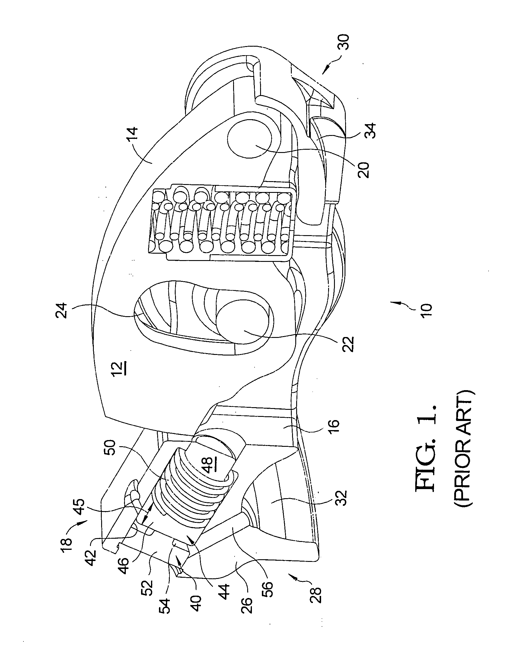
[0021]The advantages and benefits afforded to a two-step roller finger follower (RFF) in accordance with the invention may be better appreciated by first considering a prior art two-step roller finger follower. Such a two-step RFF is suitable for use in a variable valve activation system of an internal combustion engine.

[0022]Referring to FIG. 1, the view shown represents a section cutaway along a vertical symmetry plane for description purpose such that only one-half of a prior art two-step roller finger follower (RFF) 10 is present. Thus, where appropriate, the described elements should be considered as having matching counterparts (not shown) in the full RFF. A high-lift follower 12 including a cam-follower surface 14 is disposed in a central opening 16 in a rocker arm 18. High-lift follower 12 pivots within opening 16 about a pivot shaft 20. A roller shaft 22 mounted in rocker arm 18 supports a roller 24 for following a low-lift lobe of an engine camshaft (not shown).

[0023]Rocke...


PUM


Abstract

A latching mechanism for variably activating an engine valve in an internal combustion engine includes a rocker arm body having a bore and a socket. A first passage leads from the socket to a first hydraulic chamber formed above a lock pin head. A second passage leads from the socket to a second hydraulic chamber formed below the lock pin head. Since both the first and the second hydraulic chamber receive pressurized oil, it is the diameter of the pin shank that determines the hydraulic force needed to axially move the locking pin to an extended position and into a locking engagement with a slider member. In an alternate embodiment of the invention the first passage connecting the first hydraulic chamber with the socket is eliminated and instead the locking pin is modified to permit flow between second hydraulic chamber and first hydraulic chamber.

Description

TECHNICAL FIELD[0001]The present invention relates to mechanisms for altering the actuation of valves in internal combustion engines; more particularly, to finger follower type rocker arm assemblies capable of changing between high and low or no valve lifts; and most particularly, to an improved oil circuit for a latching mechanism for a two-step finger follower type rocker arm assembly.BACKGROUND OF THE INVENTION[0002]Variable valve activation (VVA) mechanisms for internal combustion engines are well known. It is known to be desirable to lower the lift, or even to provide no lift at all, of one or more valves of a multiple-cylinder engine, during periods of light engine load. Such deactivation or cam profile switching can substantially improve fuel efficiency.[0003]Various approaches are known in the prior art for changing the lift of valves in a running engine. One known approach is to provide a latching mechanism in the hydraulic lash adjuster (HLA) pivot end of a rocker arm cam ...

Claims


Application Information

Patent Timeline
Patent Type & Authority Applications(United States)
IPC IPC(8): F01L1/18
CPCF01L1/185F01L2105/00F01L13/0036F01L13/0005F01L2001/186F01L2305/00
Inventor HENDRIKSMA, NICK J.
Owner DELPHI TECH INC
Why Eureka
Try Eureka