
Method of Generating a Non-Plugging Hydrate Slurry

a technology of hydrate slurry and hydrate, which is applied in the direction of sealing/packing, borehole/well accessories, insulation, etc., can solve the problems of natural gas hydrates in transportation pipelines and equipment, costly and time-consuming procedures, and the need for restoring flow, so as to reduce the droplet size of said water and increase the fluid viscosity

Active Publication Date: 2009-03-26
EXXONMOBIL UPSTREAM RES CO
View PDF100 Cites 26 Cited by
  • Summary
  • Abstract
  • Description
  • Claims
  • Application Information

AI Technical Summary

Benefits of technology

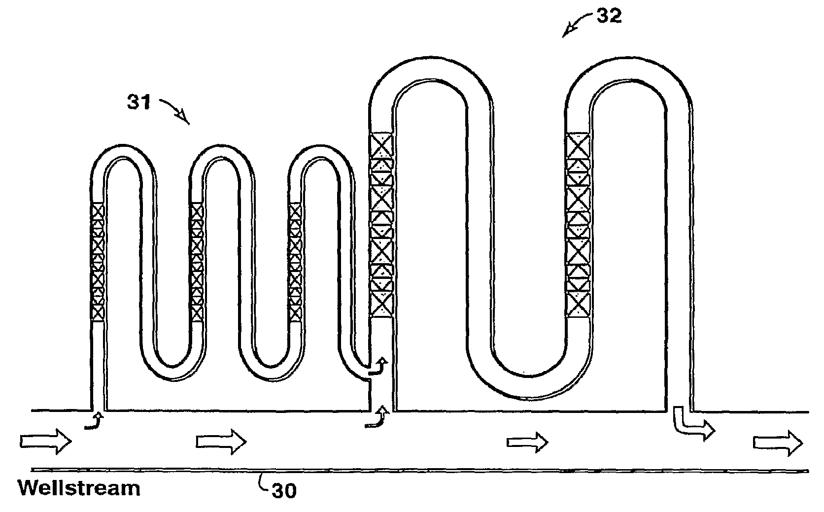
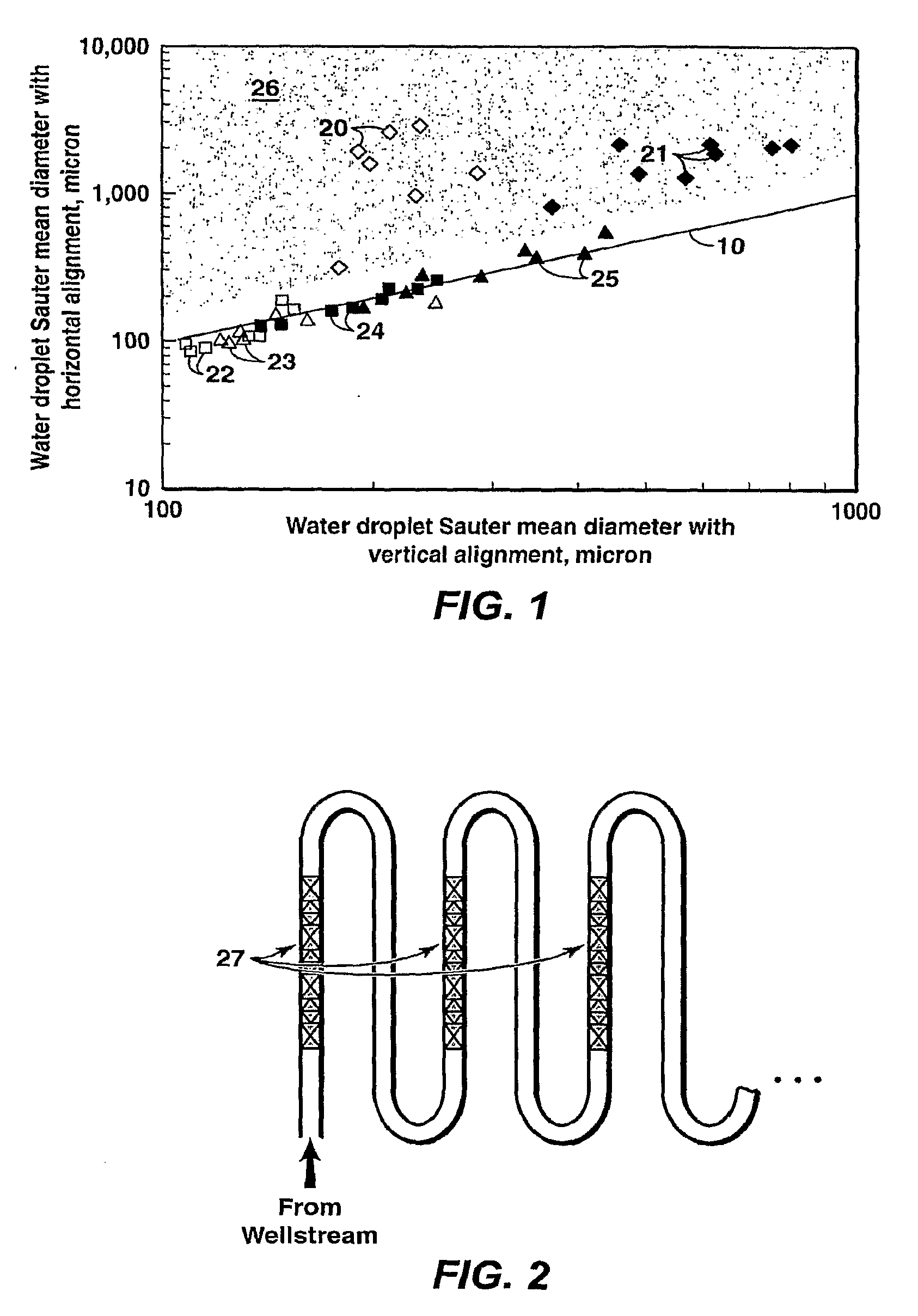
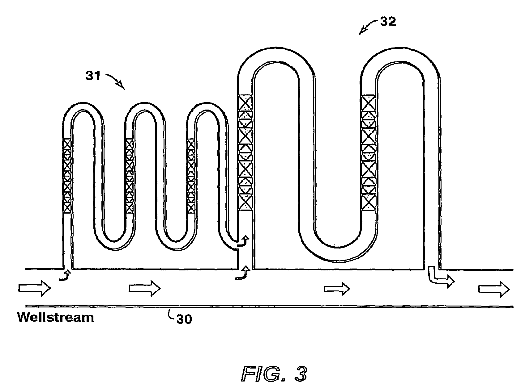
[0030]In still further embodiments, there is provided a method of producing dry hydrates, comprising: passing a hydrocarbon stream comprising water and one or more hydrate-forming gases through a cold-flow reactor, said cold-flow reactor having one or more static mixers disposed therein; reducing the droplet size of said water in said hydrocarbon stream by passing said hydrocarbon stream through said one or more static mixers; and converting at least a portion of said water into dry hydrates. The cold-flow reactor can be positioned within or form part of a pipeline for transporting the hydrocarbons. Alternatively, the cold-flow reactor can be positioned external to the pipeline for transporting the hydrocarbons, in which case the cold-flow reactor receives a sidestream of the hydrocarbons.
[0031]According to yet another aspect of the invention, there is provided a method of avoiding wax deposition and rendering a pumpable fluid of liquid hydrocarbon and wax components, comprising conveying said fluid through a pipe connected to a reactor comprising a static mixer and through said reactor before and while the fluid temperature drops below the wax appearance temperature. The fluids are mixed by their action in the area of the static mixer(s), resulting in fine wax solids that are conveyed with the fluid rather than coated / deposited on the pipe wall. The fluids are then conveyed to a processing facility without materially increasing the fluid viscosity.

Problems solved by technology

Among the most challenging problems in oil and gas production is the presence of natural gas hydrates in transport pipelines and equipment.
Also very problematic is wax deposition in flow lines.
Costly and time-consuming procedures may be needed to restore flow again in a pipeline plugged with hydrates and / or wax.
In addition to the mere economic consequences, there are also numerous hazards connected to hydrate formation and removal, and there are known instances of pipeline ruptures and loss of human lives due to gas hydrates in pipelines.
Although hydrate is generally thought of as a problem mostly for gas production, there is now ample evidence that it is also a significant problem for condensate and oil production systems.
Wax deposition is also a costly problem when produced fluids naturally contain wax compounds, usually paraffin, that coat flow lines during liquid hydrocarbon production.
In such methods, the continuous recycling of even dry hydrates in a recycle loop leads to the continued growth of the hydrates and the formation of larger and larger hydrates that, if not continuously ground into smaller hydrates using a grinder or similar equipment, would ultimately grow large enough to cause plugging.
Unfortunately, the pump or grinder is an energized piece of rotating equipment that can pose problems in subsea applications.
There are two problems with such subsea electrical rotating equipment.
First, the reliability of rotating equipment is not yet sufficient to plan for long-term operation without multiple equipment replacements during the typical lifetime of a subsea pipeline.
Second, electrical power transmission is limited in distance, thus limiting the distance over which some cold flow processes are useful.
Besides the problems of energized, rotating equipment in subsea applications, other problems occur with current cold flow methods, such as fluids forming “sticky hydrates”.
Many of the prior art methods use equipment that is not commercially proven and some of them require electricity.
In addition, many require maintenance that is particularly costly in subsea applications.

Method used


Image

  • Method of Generating a Non-Plugging Hydrate Slurry
  • Method of Generating a Non-Plugging Hydrate Slurry
  • Method of Generating a Non-Plugging Hydrate Slurry

Examples


Embodiment Construction

[0050]In the following detailed description, the specific embodiments of the present invention are described in connection with its preferred embodiments. However, to the extent that the following description is specific to a particular embodiment or a particular use of the present techniques, it is intended to be illustrative only and merely provides a concise description of the exemplary embodiments. Accordingly, the invention is not limited to the specific embodiments described below, but rather; the invention includes all alternatives, modifications, and equivalents falling within the true scope of the appended claims.

[0051]The present invention provides the use of dry hydrates and solidifying wax in a way that does not present problems associated with prior art teachings. The present invention also provides methods of seeding and / or making of dry hydrates without the aid of chemicals and with minimum use of rotating or other energized equipment.

[0052]The present invention is fu...


PUM


Abstract

Method for reducing loss of flow due to hydrate solids deposits and wax deposition in a pipeline without the aid of chemicals and system for transporting a flow of wellstream hydrocarbons containing water, using a main pipeline and a cold-flow reactor connected to the main pipeline or within or forming a part of the pipeline, wherein at least a portion of the wellstream is fed to the cold-flow reactor. Also provided is a method for preventing hydrate nucleation and growth in a pipeline and preventing hydrate agglomeration as well as for preventing wax deposition. The provided method eliminates the use of energized equipment for melting, grinding or scraping hydrate solids from inside of pipelines or flowlines. Generating dry hydrates to be mixed with main flow of a wellstream is also described.

Description

CROSS REFERENCE TO RELATED APPLICATIONS[0001]This application claims the benefit of U.S. Provisional Application No. 60 / 782,449, filed 15 Mar. 2006 and the benefit of U.S. Provisional Application 60 / 899,000, filed 2 Feb. 2007.BACKGROUND OF THE INVENTION[0002]1. Field of the Invention[0003]Embodiments of the present invention relate to seeding and / or making of dry hydrates and avoiding wax deposition without the aid of chemicals and with minimum use of rotating or other energized equipment. Other embodiments relate to the prevention of hydrate agglomeration and the prevention of wax deposition in a pipeline. The invention also relates to elimination of the use of energized equipment for melting, grinding or scraping hydrate solids and deposited waxes from inside of pipelines or flowlines. Also eliminated is the need for any recycle loops. In yet another embodiment there is no need for splitting the wellstream into two streams. In another aspect, the invention also avoids the use of r...

Claims


Application Information

Patent Timeline
Patent Type & Authority Applications(United States)
IPC IPC(8): E21B37/06E21B33/08E21B37/00
CPCB01F5/061B01F13/1013B08B9/027F17D1/16B01F13/1016E21B43/00Y10T137/0324Y10T137/206Y10T137/4238Y10T137/0391B01F25/431B01F33/811B01F33/81
Inventor TALLEY, LARRY D.TURNER, DOUGLAS J.PRIEDEMAN, DOUGLAS K.
Owner EXXONMOBIL UPSTREAM RES CO
Learn More