Method and apparatus for a high-resolution three dimensional confocal scanning transmission electron microscope

a transmission electron microscope and high-resolution technology, applied in the field of electron microscopy, can solve the problems of inability to achieve high-resolution confocal scanning transmission electron microscopes, and inability to achieve high-resolution confocal scanning electron microscopes. achieve the effect of reducing the amount of radiation

Inactive Publication Date: 2009-03-26
UT BATTELLE LLC
View PDF4 Cites 45 Cited by
  • Summary
  • Abstract
  • Description
  • Claims
  • Application Information

AI Technical Summary

Benefits of technology

[0017]Yet another advantage of at least one embodiment of the present invention is that the apparatus is relatively easily built with existing components.
[0018]Yet other advantages of at least one embodiment of the present invention are that alignment of the electron beam is straightforward and there are no dynamically synchronized beam scans, which have been shown in the prior art to be practically almost impossible to implement.
[0019]Yet another advantage of at least one embodiment of the present invention is that there is also no need for tilt-series.
[0020]Yet another advantage of a

Problems solved by technology

The main disadvantage of confocal laser microscopy is that the resolution is not better than a few hundreds of nanometers (nm), due to the wavelength of light.
But all techniques have their disadvantages.
NMR has limited applicability and requires large quantities of a sample in solution, X-ray crystallography requires high-quality crystals with many repeating units of the object of interest, AFM is a surface technique only, electron tomography has many practical difficulties due the required tilt series and has limited resolution.
The reason for this is that the amount of back-scattered electrons wit

Method used


Image

  • Method and apparatus for a high-resolution three dimensional confocal scanning transmission electron microscope
  • Method and apparatus for a high-resolution three dimensional confocal scanning transmission electron microscope
  • Method and apparatus for a high-resolution three dimensional confocal scanning transmission electron microscope

Examples


Embodiment Construction

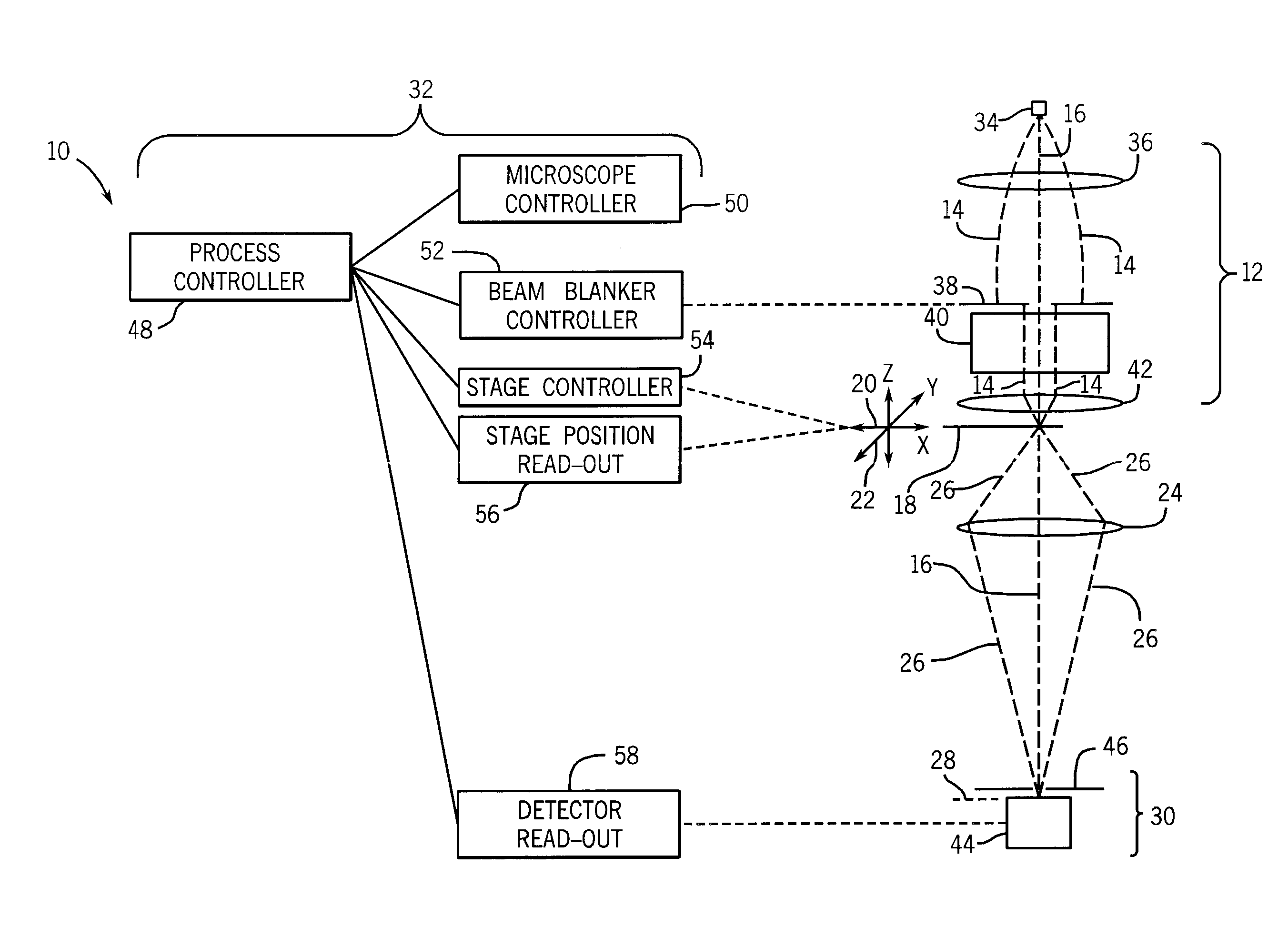
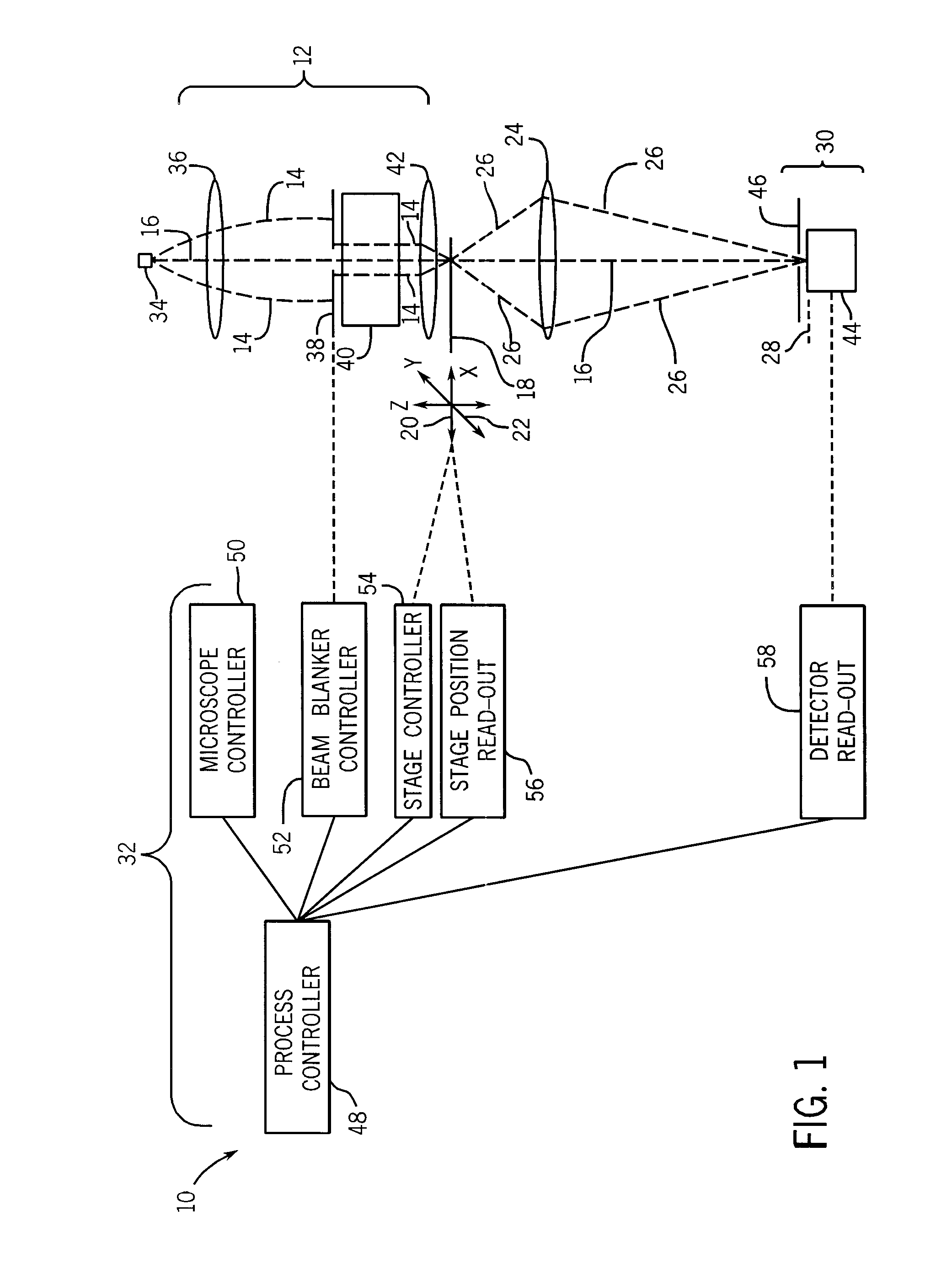
[0031]Referring now to drawings, and more particularly to FIG. 1, there is shown a confocal scanning transmission electron microscope 10 which includes an electron illumination device 12 providing an incident electron beam 14 propagating in a direction defining a propagation axis 16 (optical axis). A precision specimen scanning stage 18 is positioned along propagation axis 16 and movable in a first direction 20 and a second direction 22 along a plane defined by these two intersecting directions, and which plane is transverse to propagation axis 16; and movable in a third Z direction which is parallel to, or along, the propagation axis 16. First direction 20, second direction 22, and propagation axis 16 can define three orthogonal axes, although other configurations are possible. Alternatively, for example, the first direction can be a radial direction and the second direction can be an angular direction as in polar coordinates. Additionally, instead of three orthogonal translation d...


PUM


Abstract

A confocal scanning transmission electron microscope which includes an electron illumination device providing an incident electron beam propagating in a direction defining a propagation axis, and a precision specimen scanning stage positioned along the propagation axis and movable in at least one direction transverse to the propagation axis. The precision specimen scanning stage is configured for positioning a specimen relative to the incident electron beam. A projector lens receives a transmitted electron beam transmitted through at least part of the specimen and focuses this transmitted beam onto an image plane, where the transmitted beam results from the specimen being illuminated by the incident electron beam. A detection system is placed approximately in the image plane.

Description

STATEMENT REGARDING FEDERALLY SPONSORED RESEARCH[0001]This invention was made with assistance under Contract No. DE-AC05-00OR22725 with the U.S. Department of Energy. The Government has certain rights in this invention.BACKGROUND OF THE INVENTION[0002]The present invention relates to electron microscopy, and, more particularly, to a method and apparatus for a confocal scanning transmission electron microscope.[0003]The imaging of samples with high resolution and in three dimensions is of critical importance for many fields, such as biology, materials science and semi-conductor development, among others. One of the major tools in modern biology research is the confocal laser microscope (M. Minsky, “Memoir on Inventing the Confocal Scanning Microscope”, Scanning (USA) 10, 128-138, 1988). The principles and elements of operation include a laser beam focused by an objective lens on a sample at a certain focal plane. The back-scattered light, often from fluorescent markers, is separated ...

Claims


Application Information

Patent Timeline
IPC IPC(8): G01N23/04
CPCH01J37/26H01J37/263H01J37/265H01J2237/045H01J2237/20228H01J2237/2803H01J2237/21H01J2237/226H01J2237/24455H01J2237/262H01J2237/2802H01J2237/20235
Inventor DE JONGE, NIELS
Owner UT BATTELLE LLC
Why Eureka
Try Eureka