
Valve opening and closing control apparatus

a valve opening and closing control and valve technology, applied in the direction of valve operating means/release devices, electric control, machines/engines, etc., can solve the problems of reducing the time required for the deposit scraping action, preventing the valve from sticking, and limiting the generation of a hitting sound

Inactive Publication Date: 2009-03-26
DENSO CORP
View PDF8 Cites 36 Cited by
  • Summary
  • Abstract
  • Description
  • Claims
  • Application Information

AI Technical Summary

Benefits of technology

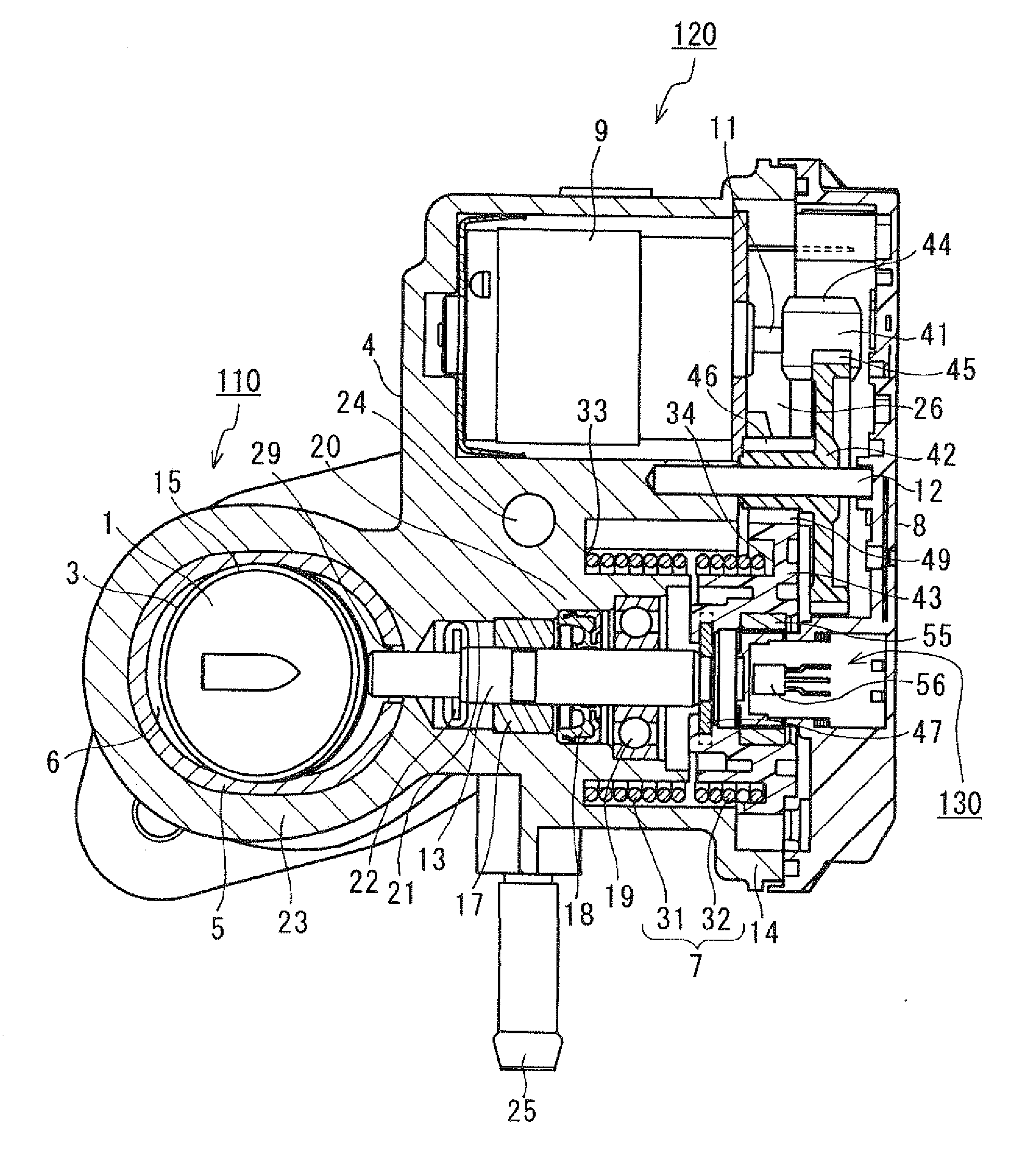
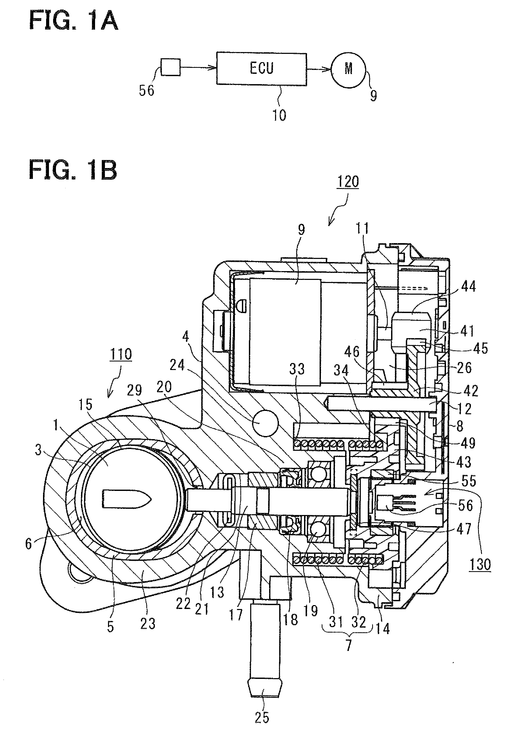
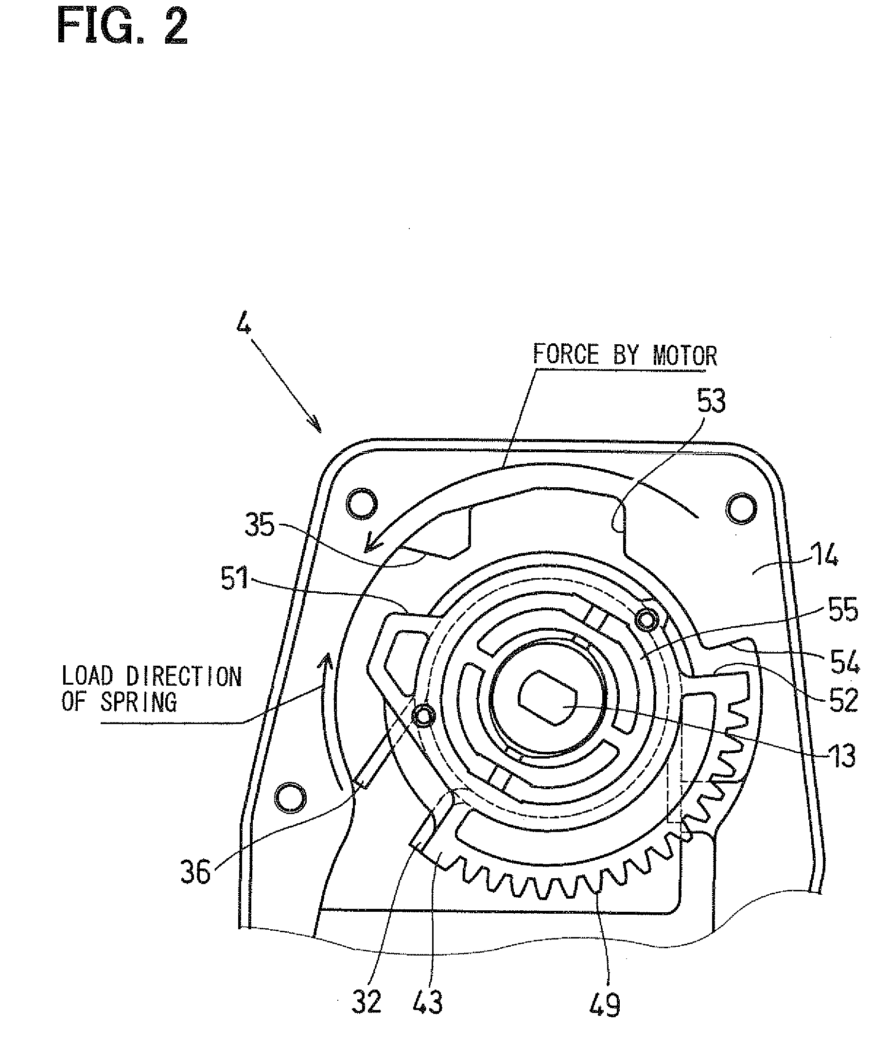
The present invention provides a valve opening and closing control apparatus that can limit the generation of hitting sound caused by collision between tooth surfaces of adjacent gears during a deposit scraping action. The apparatus includes a fluid control valve device, an actuator, valve position sensing means, and a control unit. The control unit variably controls the electric power supplied to the electric motor in such a manner that the valve position, which is sensed with the valve position sensing means, coincides with a control target value of the valve. The control unit repeats the valve opening and closing movement of the valve within a predetermined valve opening degree range between a first intermediate position and a second intermediate position through a neutral position. The urging force of the first valve urging means is balanced with the urging force of the second valve urging means at the neutral position. The apparatus can limit the generation of hitting sound and improve the performance of the internal combustion engine.

Problems solved by technology

In the case where the deposit is adhered or accumulated around the valve of the EGR control valve, when a viscosity of the deposit becomes relatively high upon dropping of the temperature of the deposit after engine stop, valve sticking (sticking of the valve caused by the viscous deposit) may possible occur due to the solidification of the deposit.
When the valve moving speed is reduced, the time required for the deposit scraping action is disadvantageously lengthened.
Thereby, a risk in terms of a vehicle burglar security is disadvantageously increased in a vehicle having a burglarproof security system.
Thus, the EGR quantity may possibly become excessive relative to the intake air quantity.
When the EGR quantity becomes excessive relative to the intake air quantity, a misfire of the internal combustion engine may occur.
This may lead to an engine stall, and thereby the vehicle may not be driven.

Method used


Image

  • Valve opening and closing control apparatus
  • Valve opening and closing control apparatus
  • Valve opening and closing control apparatus

Examples


Embodiment Construction

[0028]An embodiment of the present invention will be described with reference to FIGS. 1A to 5.

[0029]A control system of an internal combustion engine (hereinafter, simply referred to as an engine) installed in an engine room of a vehicle according to the present embodiment is used as an EGR control system (exhaust gas recirculation control system) of the engine, which controls a recirculation quantity (also referred to as an EGR quantity, an EGR ratio) of exhaust gas (EGR gas) that is recirculated into an intake system from an exhaust system of the engine based on an operational state of the engine.

[0030]The EGR control system (a valve opening and closing control apparatus) of the engine according to the present embodiment includes an intake pipe, an exhaust pipe, an exhaust gas recirculation pipe, an exhaust gas recirculation control valve (also referred to as an exhaust gas control valve, an EGR control valve, and will be hereinafter referred to as an EGRV) 110 and a valve openin...


PUM


Abstract

When a control unit variably controls an electric power supplied to an electric motor to repeat a valve opening and closing movement of a valve between a first intermediate position and a second intermediate position through a neutral position, the control unit initially sets the neutral position as a control target value until a valve position, which is sensed with a valve opening degree sensor, is located immediately before the neutral position. The control unit thereafter changes the control target value to the first intermediate position or the second intermediate position when the control unit determines that the valve position, which is sensed with the valve opening degree sensor, reaches the neutral position.

Description

CROSS REFERENCE TO RELATED APPLICATION[0001]This application is based on and incorporates herein by reference Japanese Patent Application No. 2007-243259 filed on Sep. 20, 2007.BACKGROUND OF THE INVENTION[0002]1. Field of the Invention[0003]The present invention relates to a valve opening and closing control apparatus, which drives a valve.[0004]2. Description of Related Art[0005]In order to reduce noxious components (e.g., nitrogen oxide also called as NOx) contained in the exhaust gas outputted from each combustion chamber of the internal combustion engine (e.g., a diesel engine), an exhaust gas recirculation apparatus, which includes an exhaust gas recirculation pipe and an EGR control valve, has been proposed (see, for example, Japanese Unexamined Patent Publication No. 2005-233063). The exhaust gas recirculation pipe recirculates a portion of the exhaust gas, which is outputted from each combustion chamber of the internal combustion engine, into an intake system of the internal...

Claims


Application Information

Patent Timeline
Patent Type & Authority Applications(United States)
IPC IPC(8): F16K31/04
CPCF02D41/0077F02D41/2464F02D2250/16Y02T10/47F02M25/0773F02M25/0794F16K31/046F02M25/0756F02M26/48F02M26/54F02M26/72Y02T10/40
Inventor SASAKI, KAZUSHISHIMANE, OSAMU
Owner DENSO CORP
Learn More