Disk device
a technology of a disk and a head is applied in the field of disk devices, which can solve the problems of data not being read, data not being able to be recorded, and the precise following of the magnetic head to the data track is difficult, so as to achieve stable head levitation and head output, the effect of preventing contact between the head and the disk and reducing the thickness
- Summary
- Abstract
- Description
- Claims
- Application Information
AI Technical Summary
Benefits of technology
Problems solved by technology
Method used
Image
Examples
embodiment 1
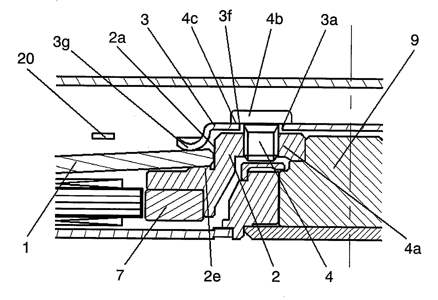
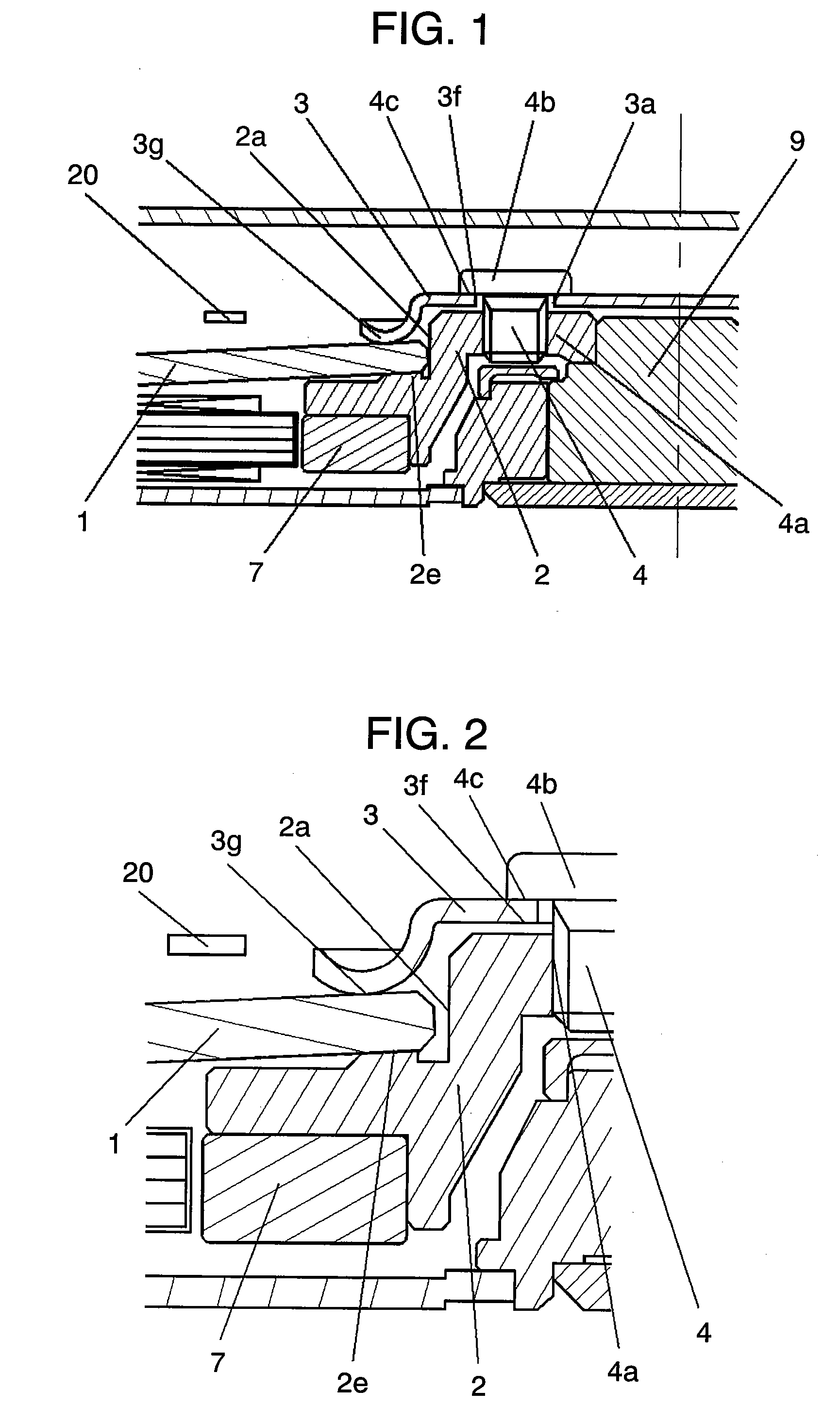
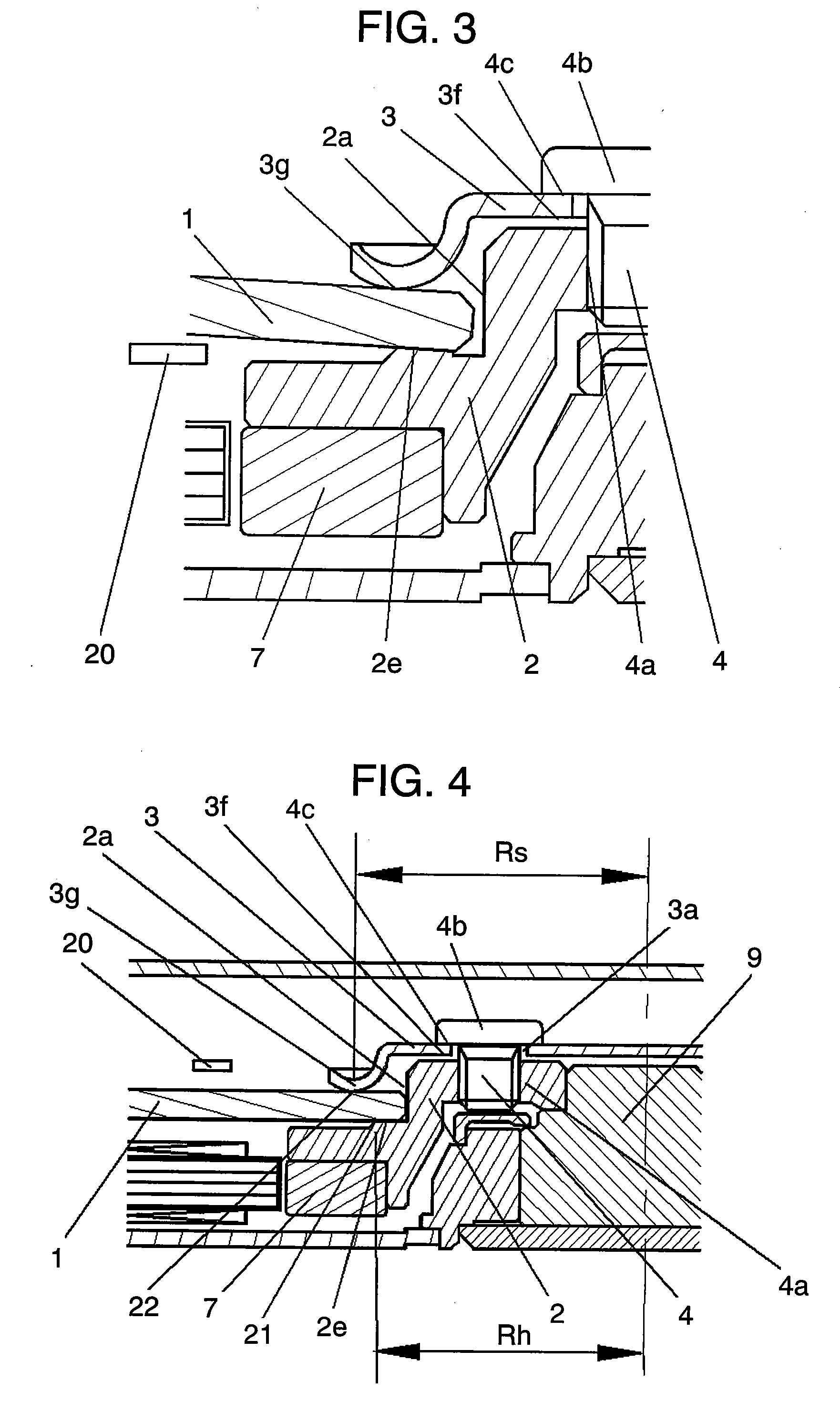
[0092]A disk apparatus according to Embodiment 1 of the invention will be described with reference to FIGS. 1 to 3. FIG. 1 is a partial section view showing a schematic structure of a disk apparatus according to Embodiment 1 of the invention. FIG. 2 is an enlarged section view showing a clamp structure of the disk apparatus according to Embodiment 1 of the invention. FIG. 3 is an enlarged section view showing a clamp structure of another disk apparatus according to Embodiment 1 of the invention. In FIGS. 1 to 3, the same reference numerals are given to the same components as those in FIGS. 16 and 17, which describe the construction of a conventional disk apparatus.
[0093]In FIGS. 1 and 2, disk-shaped recording medium 1 (where a disk-shaped recording medium is abbreviated to disk hereinafter) having a hole in the inner part is inserted to disk inserting portion 2a cylindrically projecting from hub 2. One face of disk 1 is received by the top face of disk receiving portion 2e in the ou...
embodiment 2
[0097]Next, a disk apparatus according to Embodiment 2 of the invention will be described with reference to FIGS. 4 to 7. FIG. 4 is a partial section view showing a schematic structure of a disk apparatus according to Embodiment 2 of the invention. FIG. 5 is an enlarged section view showing a clamp structure of the disk apparatus according to Embodiment 2 of the invention. FIG. 6 is a correlation diagram showing a relationship between distance Rh and distance Rs and amounts of warps of the disk, which are produced by clamping the disk. FIG. 7 is an enlarged section view showing a clamp structure of another disk apparatus according to Embodiment 2 of the invention. In FIGS. 4, 5 and 7, the same reference numerals are given to the same components as those in FIGS. 1, 2 and 3, which describe the construction of the disk apparatus according to Embodiment 1 of the invention.
[0098]In FIGS. 4 and 5, disk 1 having a hole in the inner part is inserted to disk inserting portion 2a cylindrical...
embodiment 3
[0107]Next, a disk apparatus according to Embodiment 3 of the invention will be described with reference to FIGS. 8 to 15. FIG. 8 is a partial section view showing a schematic structure of a disk apparatus according to Embodiment 3 of the invention. FIG. 9 is an enlarged section view showing a clamp structure of the disk apparatus according to Embodiment 3 of the invention. FIG. 10 is a correlation diagram showing a relationship between contact points Rh between a clamp member and a disk and between the disk and a hub, which are produced by warping of the disk due to clamping and the radius of curvature of the warping of a disk. FIG. 11 includes diagrams describing relationships between the amounts of head levitation and head gaps when the disk warps. FIG. 12 includes diagrams describing relationships between the amounts of head levitation and head gaps due to a warp of a disk when the disk and head have a rate of warping. FIG. 13 is a diagram showing deformation of the disk, which ...
PUM
| Property | Measurement | Unit |
|---|---|---|
| Young's modulus | aaaaa | aaaaa |
| flatness | aaaaa | aaaaa |
| frictional coefficient | aaaaa | aaaaa |
Abstract
Description
Claims
Application Information
 - R&D
- Intellectual Property
- Life Sciences
- Materials
- Tech Scout
- Unparalleled Data Quality
- Higher Quality Content
- 60% Fewer Hallucinations
Browse by: Latest US Patents, China's latest patents, Technical Efficacy Thesaurus, Application Domain, Technology Topic, Popular Technical Reports.
© 2025 PatSnap. All rights reserved.Legal|Privacy policy|Modern Slavery Act Transparency Statement|Sitemap|About US| Contact US: help@patsnap.com


