

NANO coating for EMI gaskets
a gasket and nano coating technology, applied in the field of nanoparticles, can solve the problems of electromagnetic radiation passage, adversely affecting the performance of an electronic circuit, and causing electromagnetic interferen
Inactive Publication Date: 2009-04-02
PARKER HANNIFIN CORP
View PDF13 Cites 60 Cited by
- Summary
- Abstract
- Description
- Claims
- Application Information
AI Technical Summary
Benefits of technology
The present invention provides an EMI shielding gasket that can be used to protect electronic equipment from electromagnetic interference (EMI) and radiofrequency interference (RFI). The gasket has a resilient core and a conductive coating or ink containing nanoparticles made of materials like carbon or silver. The nanoparticles are incorporated into a polymer or ink which is applied to the gasket's surface. The coating or ink is thick enough to provide effective shielding but thin enough to not compromise the gasket's flexibility. The gasket can be used in electronic enclosures like computer cabinets and drives, providing both EMI and RFI shielding. The coating or ink can be cured at high temperatures or room temperature depending on the polymer and solvent used.
Problems solved by technology
As is known in the art, EMI is radiated or conducted energy that adversely affects the performance of an electronic circuit.
The increasing operating frequency in commercial electronic enclosures, such as computers and automotive electronic modules, results in an elevated level of high frequency electromagnetic interference (EMI).
Any gap between the metal surfaces mating with doors and access panels of the enclosures for these devices affords an opportunity for the passage of electromagnetic radiation and the creation of electromagnetic interference (EMI).
These gaps also interfere with the electric currents running along the surfaces of the cabinets from EMI energy, which is absorbed and is conducted to the ground.
If not properly shielded, such radiation can cause considerable interference with unrelated equipment.
Between even the flattest of these accesses and its corresponding mating or faying surface, however, gaps may be present which reduce the efficiency of the shielding by containing openings through which radiant energy may leak or otherwise pass into or out of the device.
Moreover, such gaps represent discontinuities in the surface and ground conductivity of the housing or other shielding, and may even generate a secondary source of EMI radiation by functioning as a form of slot antenna.
While the aforementioned and other known gaskets perform reasonably well, these gaskets are relatively costly to assemble in a cabinet.
Moreover, the tightly knit wire mesh necessitates that a high closure force is required to seal the door or panel, and the combination of the tightly knit mesh and the required metal clip makes the gasket heavy, which is detrimental in applications where weight is a critical factor such as in the aerospace industry.
Method used
View moreImage
Smart ImageViewing Examples

Examples
examples
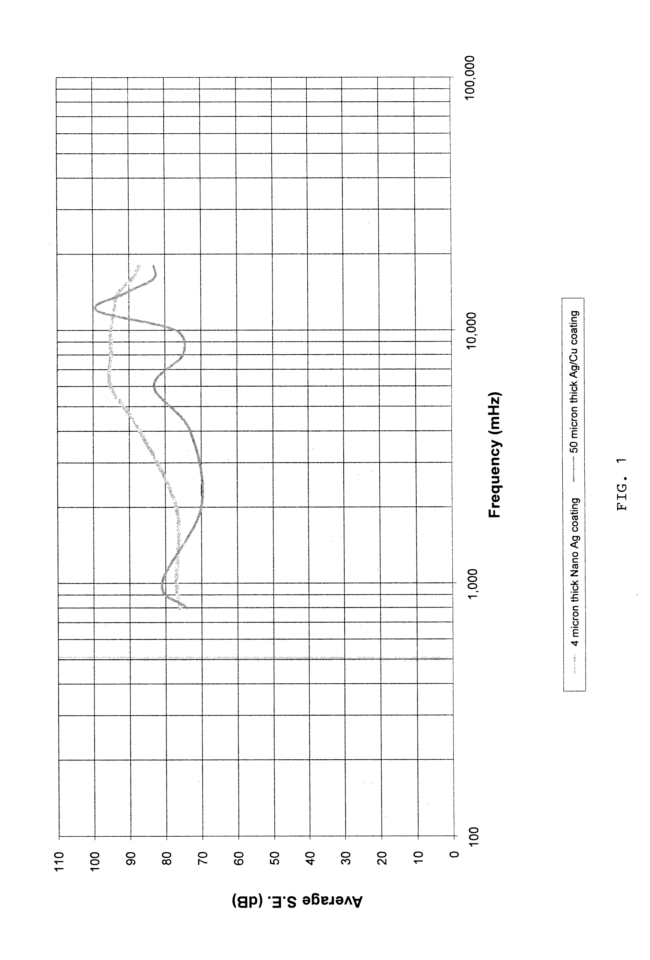
[0044]A conductive nanoparticle ink formulation was obtained from PChem Associates. The ink, designated as PF1200, is an aqueous formulation containing spherical silver nanoparticles having a nominal size of about 15 mm.
[0045]A gasket was coated with the ink using a dip coating process to form a continuous coating over the gasket. A similar gasket was coated with a conventional silver / copper coating. The results are shown in FIG. 1 for comparison wherein the shielding effectiveness is plotted against frequency for each coating.
Login to View More PUM
| Property | Measurement | Unit |
|---|---|---|
| thickness | aaaaa | aaaaa |
| thickness | aaaaa | aaaaa |
| sizes | aaaaa | aaaaa |
Abstract
EMI shielding gaskets prepared by coating a resilient nonconductive core gasket with a coating or ink containing conductive nanoparticles. The coating layer can be applied at a thickness of 10 microns or less to achieve shielding levels comparable to conventional coatings which are typically an order of magnitude thicker.
Description
CROSS-REFERENCE TO RELATED APPLICATIONS[0001]This application claims the benefit of U.S. Provisional Application No. 60 / 976,937 filed on Oct. 2, 2007, the disclosure of which is incorporated herein by reference.BACKGROUND OF THE INVENTION[0002]The present invention relates to nanoparticles used as conductive fillers for electromagnetic interference (EMI) shielding coatings and inks. The coatings and inks of this invention are applied to the outer surfaces of gaskets to provide EMI shielding or radio interference (RFI) shielding.[0003]As is known in the art, EMI is radiated or conducted energy that adversely affects the performance of an electronic circuit. EMI and / or RFI may be eliminated or reduced by the use of shielded enclosures and appropriate shielding materials.[0004]The operation of electronic equipment, such as televisions, radios, computers, medical instruments, business machines, communication equipment, and the like, is typically accompanied by the generation of radio fr...
Claims
Login to View More Application Information
Patent Timeline
 Patent Type & AuthorityApplications(United States)
IPC IPC(8): H05K9/00
CPCH05K9/0015
InventorSEVERANCE, CHRISTOPHER L.
OwnerPARKER HANNIFIN CORP