Dam-free hydro-power plant

a technology of dam-free hydropower and hydropower plant, which is applied in the direction of electric generator control, renewable energy generation, greenhouse gas reduction, etc., can solve the problems of insignificant stream potential energy in such a unit, rather low efficiency, and relatively small power capacity of such hydroelectric plants

Inactive Publication Date: 2009-04-02
LYATKHER VICTOR
View PDF1 Cites 10 Cited by
  • Summary
  • Abstract
  • Description
  • Claims
  • Application Information

AI Technical Summary

Benefits of technology

[0017]The opportunity of installation of the inventive hydroelectric power plant without a dam below the water level, for example in a river, allows exploitation of the plant during the winter period, when the river is covered by ice. In other embodiments, such power plant, immersed into seawater, may operate during strong surface sea waves without significant influences therefrom.

Problems solved by technology

Such hydroelectric power plants without a dam have a deficiency in that the operation of the turbine depends on the elevation level of the water stream provided by the plate, and consequently the stream potential energy in such a unit is insignificant.
However, it has rather low efficiency that is conditioned by the fact that the pressure of water is practically created only by the tilt of riverbed, and therefore the power capacity of such hydroelectric plants is relatively small.
In addition, the slow rotation of the driving wheel of turbine requires implementation of heavy and expensive multiplying gears for transmission of the rotation to the electro-generator.
However, the necessity of raising the water stream above the river level for supplying the stream to the cut-off valve leads to additional losses of the water stream energy that reduces the efficiency of conversion of the stream energy into electric energy.
Besides, the necessity of creation of the vertical channel for water delivery to the driving wheel of turbine leads to complication of the design of such power plant, and increasing its dimensions.

Method used


Image

  • Dam-free hydro-power plant
  • Dam-free hydro-power plant

Examples


Embodiment Construction

[0019]While the invention may be susceptible to embodiment in different forms, there is shown in the drawing, and will be described in detail herein, a specific embodiment of the present invention, with the understanding that the present disclosure is to be considered an exemplification of the principles of the invention, and is not intended to limit the invention to that as illustrated and described herein.

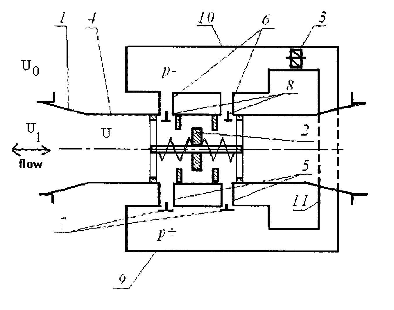
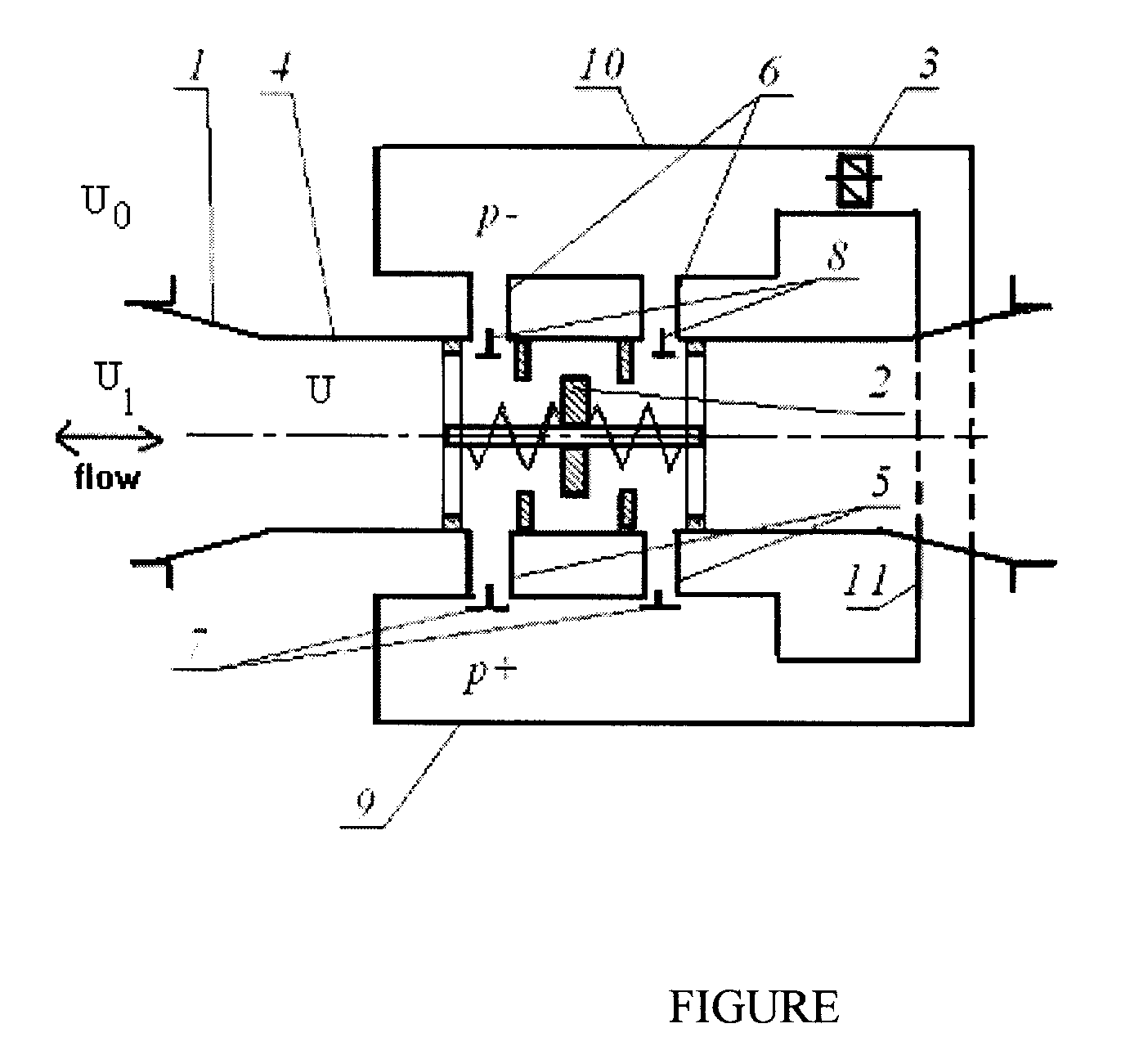
[0020]As illustrated on FIGURE, the inventive dam-free power plant comprises a water passage (1) formed in a convergent-divergent shape, having a cylindrical neck (4) situated preferably in the middle portion of the neck 1; a fast-response shutter (2) mounted in the neck 4; two cross-flow branch pipes (5) and two cross-flow branch pipes (6), each branch pipe 5 or 6 is connected with the cylindrical neck 4, each of the branch pipes 5 includes a reverse valve (7), each of the branch pipes 6 includes a reverse valve (8), wherein the valves 7 and 8 are chosen of a double-acting (bila...


PUM


Abstract

A dam-free hydro-power plant for generating electricity comprises a convergent-divergent water passage including a cylindrical neck containing a shutter, branch pipes connected with the neck, each branch pipe including a reverse valve capable of triggering, depending on the stream direction in the passage. A first and second branch pipes are located in front of the shutter, a third and fourth branch pipes are located behind thereof, a first and second buffers accumulating respectively higher-pressure liquid and lower-pressure liquid, the buffers are communicated through a cross-flow pipeline enclosing a turbine joined with an electro-generator. The first buffer is communicated with the neck via the first and the third branch pipe, whereas the second buffer is communicated with the neck via the second and the fourth branch pipe. The plant is highly efficient due to deploying hydro-impact, and particularly usable in places of tidal activities, in freezing rivers for all-year-round generating electricity.

Description

CROSS-REFERENCE TO RELATED APPLICATIONS[0001]This U.S. patent application claims priority under 35 U.S.C. 119 (a) through (d) from a Russian Federation patent application No. 2007135746 filed on 27 Sep. 2007.BACKGROUND OF THE INVENTION[0002]The invention relates to the field of hydro-power engineering, namely to hydroelectric power plants and stations, and is primarily intended for conversion of renewable energy possessed by water currents of rivers and other water reservoirs, as well as for conversion of renewable tidal energy into electric power of direct or alternating current.[0003]There is known a hydroelectric power plant including a plate, leanly submerged into water towards the water stream at ⅓ of the depth, with a takeoff of energy of the most potential upper layer of the water stream, elevating the specified layer to a predetermined height, and guiding it to a funnel-shaped mouth of a vertical cavity; and a turbine mounted at the base of the vertical cavity on a vertical ...

Claims


Application Information

Patent Timeline
Patent Type & Authority Applications(United States)
IPC IPC(8): F03B13/10
CPCF03B13/10F03B15/02F03B17/061Y02E10/28Y02E10/22Y02E10/226F05B2240/133Y10S415/906Y02E10/20Y02E10/30
Inventor LYATKHER, VICTOR
Owner LYATKHER VICTOR
Why Eureka
Try Eureka