Sealed battery

a battery and seal technology, applied in the field of sealable batteries, can solve the problems of large increase in heat, large amount of energy required in welding, and variable weldability, and achieve the effect of low occurrence of internal short circuits

Active Publication Date: 2009-04-02
SANYO ELECTRIC CO LTD
View PDF2 Cites 10 Cited by
  • Summary
  • Abstract
  • Description
  • Claims
  • Application Information

AI Technical Summary

Benefits of technology

[0013]An advantage of some aspects of the present invention is to provide a sealed battery which has exposed portions of positive electrode substrates at one end of an electrode assembly for the sealed-battery and of negative electrode substrates at the other end, and which is high-reliability with low occurrence of internal short-circuits, since the movement of spattered particles into the interior of the electrode assembly when collectors are resistance-welded to the substrates is prevented.

Problems solved by technology

Therefore, it is necessary not simply to enlarge the battery capacity, but also to increase the battery output, which exerts large effects on an automobile's acceleration and hill-climbing performance.
However, when a high output is discharged, a large current flows in the battery, and as a result there is a large increase in heat due to contact resistance between the substrates and the collectors, which are the generation elements.
Also, in order to effect low resistance, the material used for the negative electrode assembly of a lithium ion secondary battery is copper or copper alloy, which however have the characteristics of low electrical resistance and high thermal conductivity, so that an extremely large amount of energy is required in order to weld them.
There also exist the problems that when copper or copper alloy is laser-welded, the weldability varies greatly depending on the condition of the surfaces, and that the occurrence of spattering is unavoidable, as in laser welding of other materials.
Ultrasonic welding also requires a large amount of energy, because the thermal conductivity of the copper or copper alloy welded material is high.
Further, with resistance welding, due to the copper or copper alloy welded material having low electrical resistance and high thermal conductivity there exist the problems that large current needs to be input in a short time, that fusion-joining of the collectors and the electrode poles, which are of the same material as the collectors, sometimes occurs during welding, and that melting or spark generation may occur at places other than the welds.
Thus, the three welding methods have their merits and drawbacks.
However, especially in order to resistance-weld the copper collectors to the substrates of copper or copper alloy in the electrode assembly (see JP-A-2002-008708) of sealed batteries for EV and HEV application, which have exposed portions of positive electrode substrates at one end and of negative electrode substrates at the other, a great deal of welding energy is necessary in order to effect a firm weld, since the electrode assembly has a large number of stacked layers.
Moreover, when the welding energy is rendered large for resistance welding, the generation of spattered particles is increased and there is increased such a probability that the particles move into the inside of the electrode assembly, so that the internal short circuit is caused.
Typically, with such a sealed battery, a large amount of welding energy has to be applied in order to effect film welding, since the electrode assembly has a large number of stacked layers.
Further, during resistance welding, an increased amount of spattered particles are generated.
However, with the sealed battery of the above-described arrangement, since a groove is formed around the resistance-welded portion of at least any one of the collectors and the collector receiving parts, spattered particles generated during resistance welding fall within and are captured in the groove, and thus such particles rarely disperse to the interior or exterior of the electrode assembly.
Copper and copper alloys have the lowest electrical resistance and the highest thermal conductivity among the commonly-used conductive metals, and therefore generate a large amount of spattered particles during resistance welding, which requires a large current to be passed.

Method used


Image

  • Sealed battery
  • Sealed battery
  • Sealed battery

Examples


first working example

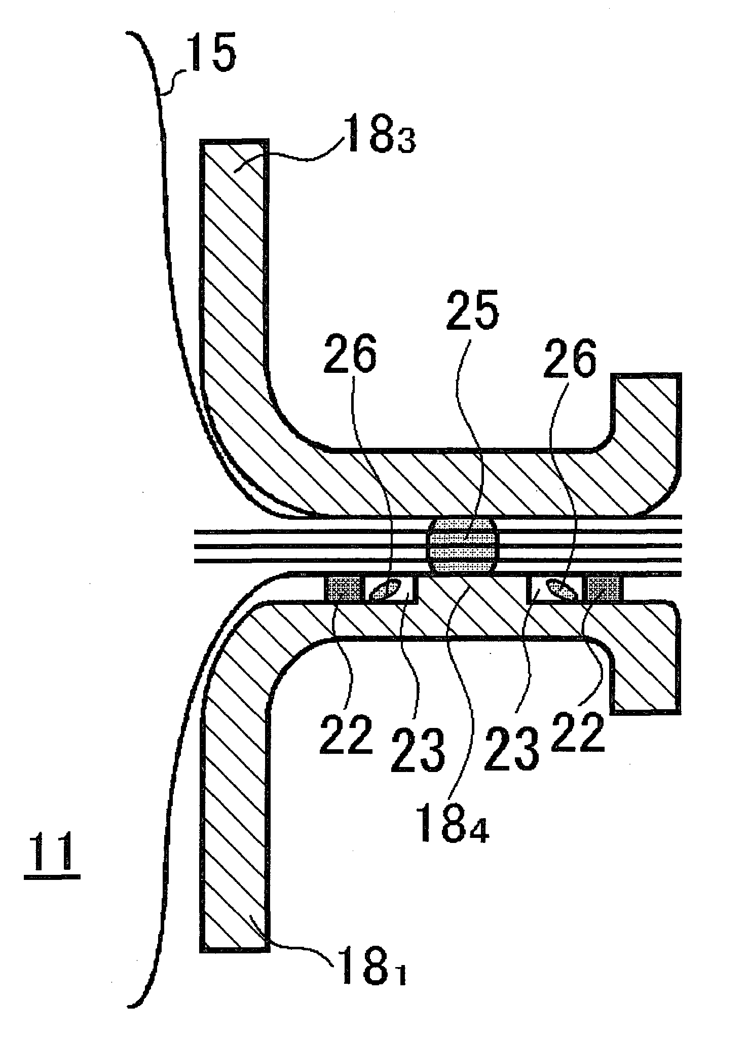
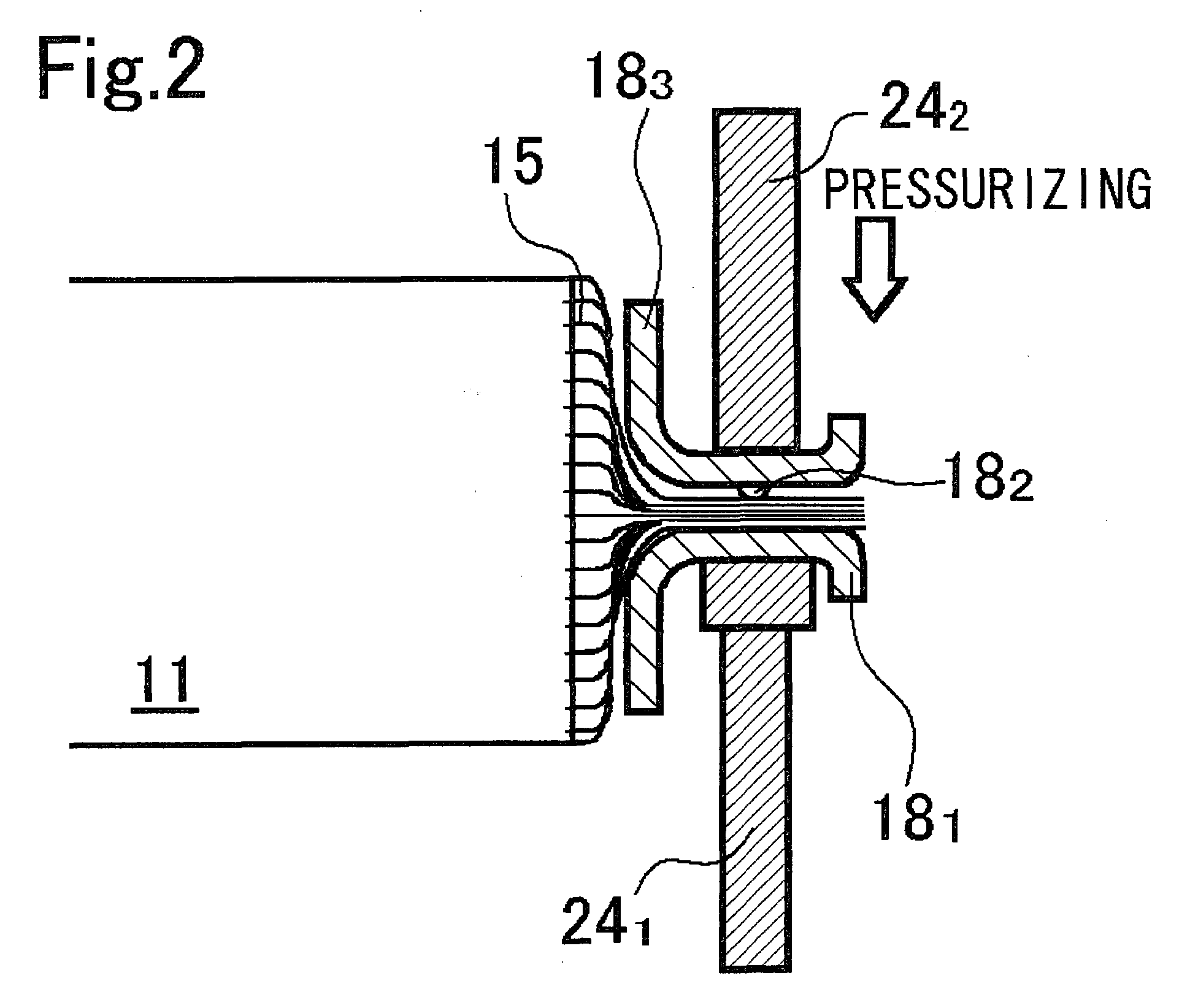
[0049]In the first working example, as shown in FIG. 2, a copper-made negative electrode collector receiving part 183 in which a tapered protuberance 182 (having a height of 0.8 mm and a diameter of the bottom part of 2 mm) functioning as a projection is formed in the central part thereof, was used. Then, as shown in FIG. 3, a copper-made negative electrode collector 181 in which a flat-surfaced protuberance 184 in a columnar shape having a diameter of 4 mm and a height of 0.5 mm is formed in the central part thereof was used. Surrounding the flat-surfaced protuberance 184 and departing from the protuberance 184 by 1 mm, an insulating tape layer 22 having a thickness of about 0.5 mm produced by laminating insulating tapes (a polypropylene tape in which the substrate is made-of polypropylene tape and an adhesive is rubber-based) having a thickness of 40 μm was adhered. That is, a groove 23 formed in the negative electrode collector 181 of the first working example has a groove diamet...

second working example

[0051]In the second working example, the same negative electrode collector receiving part 183 as that used in the first working example was used. Then, a copper-made negative electrode collector 181 in which a flat-surfaced protuberance 184 in a columnar shape having a diameter of 20 mm and a height of 2 mm is formed in the central part thereof was used. Like in the first working example, surrounding the flat-surfaced protuberance 184 and departing from the protuberance 184 by 9 mm, an insulating tape layer having a thickness of about 2 mm produced by laminating the same insulating tapes as those in the first working example was adhered. That is, a groove 23 formed on the negative electrode collector 181 of the second working example has a groove diameter of 20 mm, a groove width of 9 mm and a groove depth of 2 mm.

[0052]In the above-described state, by performing the resistance-welding as described above, it was inspected visually whether the spattered particles splash to the outsid...


PUM

PropertyMeasurementUnit
inner diameteraaaaaaaaaa
depthaaaaaaaaaa
widthaaaaaaaaaa

Abstract

A sealed battery including: an electrode assembly 11 having multiple positive electrode substrates exposed at one end and negative electrode substrates exposed at the other end; and collectors 181 and collector receiving parts 183 that are resistance-welded on both sides of the multiple positive or the multiple negative electrode substrates or both, grooves 23 being formed around the resistance-welded portion of at least one of the collector 181 and the collector receiving part 183. Due to the spattered particles 26 generated during the resistance-welding being captured within the grooves 23, few particles burst into the inside of the electrode assembly 11 or into the outside.

Description

TECHNICAL FIELD[0001]The present invention relates to a sealed battery. More particularly it relates to a sealed battery which has exposed portions of positive electrode substrates at one end of an electrode assembly for the sealed battery and of negative electrode substrates at the other end, and which has high-reliability with low occurrence of internal short-circuits, since the movement of spattered particles into the interior of the electrode assembly when collectors are resistance-welded to the substrates is prevented.BACKGROUND ART[0002]Curbs on emissions of carbon dioxide and other substances have been strengthened against a background of a growing environmental protection movement, and in the automobile world there is now vigorous development of electric vehicles (EVs) and hybrid electric vehicles (HEVs) alongside vehicles using fossil fuels such as gasoline, diesel oil and natural gas. In addition, the soaring price of fossil fuels in recent years has acted to spur on the d...

Claims


Application Information

Patent Timeline
Patent Type & Authority Applications(United States)
IPC IPC(8): H01M2/08H01M4/00H01M50/538
CPCH01M2/263H01M4/131H01M4/133Y02T10/7011H01M10/0431H01M10/0525H01M4/661Y02E60/10H01M50/538
Inventor TANIGUCHI, YASUTOMONANSAKA, KENJIYAMAUCHI, YASUHIRONOHMA, TOSHIYUKI
Owner SANYO ELECTRIC CO LTD
Why Eureka
Try Eureka