Fuel cell system

a fuel cell and system technology, applied in the field of fuel cell systems, can solve the problems of large fuel cell system, difficult to use the fuel cell system as a stationary dispersed power generation system for household use or an electrical vehicular power plant, and damage to the fuel cell system, so as to reduce the adverse effect of the environment, reduce the effect of fuel cell system damage, and reduce the effect of fuel cell system siz

Inactive Publication Date: 2009-04-09
PANASONIC CORP
View PDF1 Cites 31 Cited by
  • Summary
  • Abstract
  • Description
  • Claims
  • Application Information

AI Technical Summary

Benefits of technology

[0061]According to the invention, an environmentally-friendly fuel cell system can be provided in which carbon monoxide emission at the start of a power generating operation can be effectively suppressed with a simple structure to mitigate the adverse effect on the ecosystem.

Problems solved by technology

In this case, if the stagnant fuel gas is mixed with air coming from the combustion burner opened to the atmosphere owing to natural convection, hydrogen contained in the fuel gas will be rapidly oxidized by oxygen contained in the air, which gives rise to a risk that the fuel cell system may be damaged by the reaction heat generated by the oxidation reaction.
This makes the fuel cell system large-sized and therefore makes it difficult to use the fuel cell system as a stationary dispersed power generation system for household use or an electrical vehicular power plant.
Furthermore, the use of the feeing means of the inert gas such as nitrogen gas in addition to the existing components increases the initial cost of the fuel cell system.
In addition, the known fuel cell system needs periodical replacement or replenishment of the inert gas feeding means such as a nitrogen cylinder, which leads to an increase in the running cost of the fuel cell system.
The reason for this is that the operating temperature of the reformer has not reached a specified value at the start of a power generating operation and therefore a sufficient amount of carbon monoxide cannot be removed from the fuel gas.
If a solid polymer electrolyte fuel cell, for example, is supplied with the fuel gas containing a high concentration of carbon monoxide, the catalyst of the fuel electrode of the solid polymer electrolyte fuel cell will be poisoned by the carbon monoxide supplied.
The poisoning of the catalyst of the fuel electrode significantly hinders the progress of the electrochemical reaction in the fuel cell.
Therefore, the known fuel cell system suffers from the problem that the power generating performance of the fuel cell deteriorates, depending upon the number of stops and starts of power generating operation.
Furthermore, periodical replacement of an inert gas (nitrogen gas) feeding means is unnecessary, which makes it possible to keep the running cost of the fuel cell system low.

Method used


Image

  • Fuel cell system
  • Fuel cell system
  • Fuel cell system

Examples


first embodiment

[0095]First of all, the details of the configuration of a fuel cell system according to a first embodiment of the invention will be described with reference to the drawings.

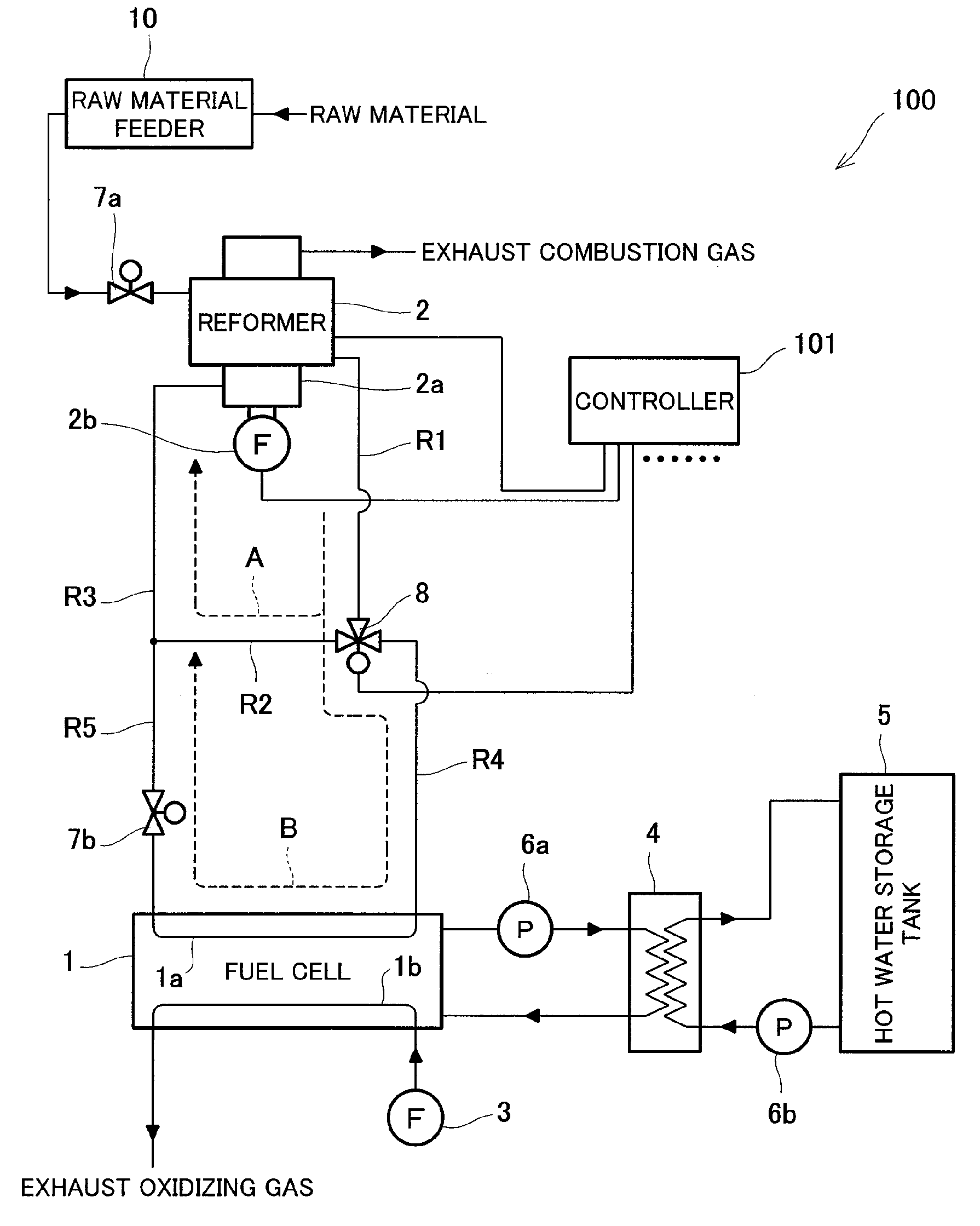
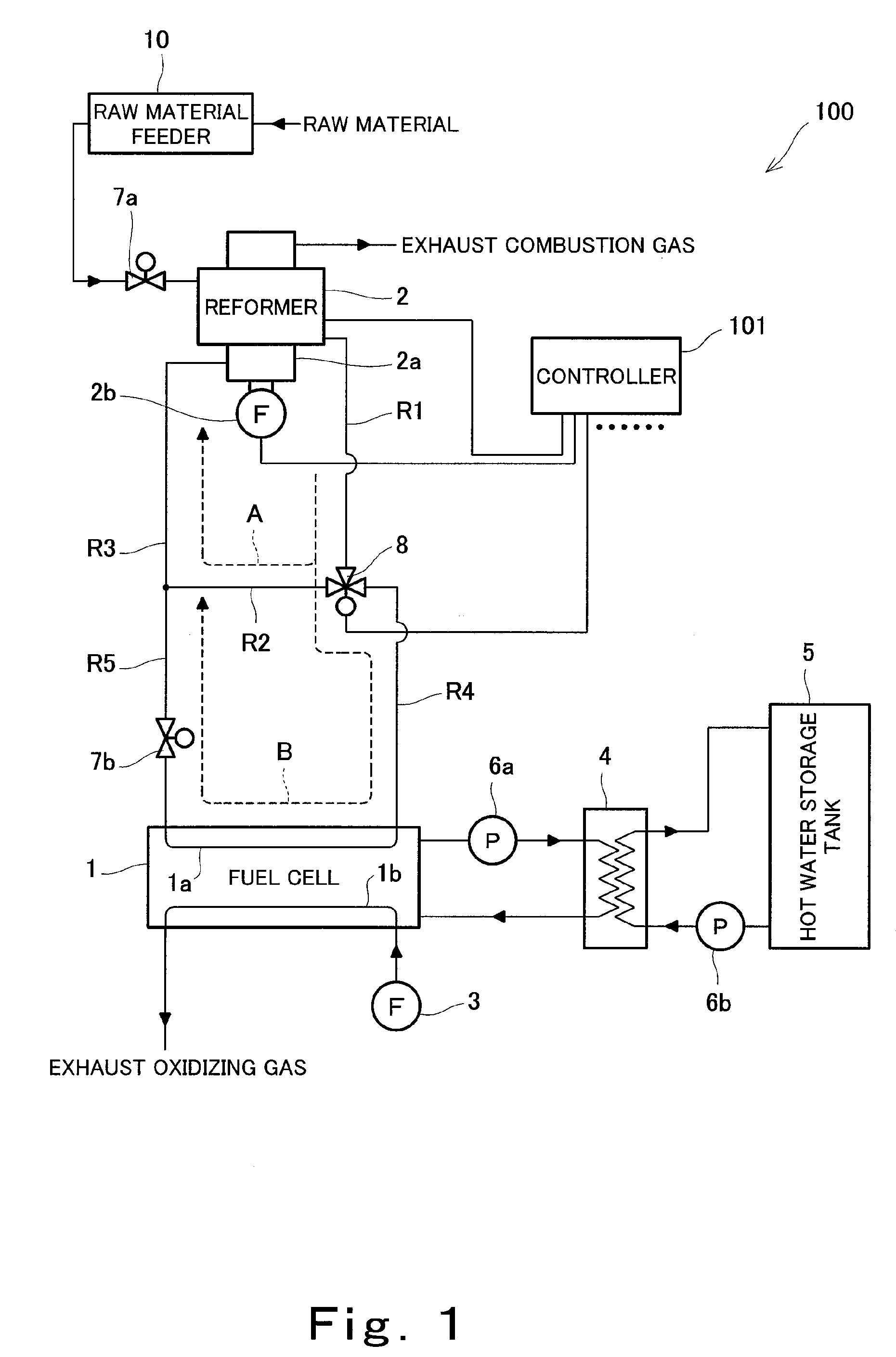
[0096]FIG. 1 is a block diagram that schematically shows the configuration of the fuel cell system according to the first embodiment of the invention. In FIG. 1, the solid lines connecting the components of the fuel cell system represent the passages where water, fuel gas, oxidizing gas, electric signals and the like flow respectively. The arrows on the solid lines indicate the flowing directions of the water, fuel gas, oxidizing gas etc., respectively when the fuel cell system is in normal operation. It should be noted that FIG. 1 shows only the components necessary for describing the invention and other components are omitted from FIG. 1.

[0097]As illustrated in FIG. 1, the fuel cell system 100 of this embodiment has a fuel cell 1 that serves as the main body of the power generating section thereof. As the fuel ...

second embodiment

[0147]FIG. 4 is a block diagram that schematically shows a configuration of a fuel cell system according to a second embodiment of the invention. In FIG. 4, the solid lines connecting the components of the fuel cell system represent the passages where water, fuel gas, oxidizing gas and the like flow respectively. The arrows on the solid lines indicate the flowing directions of the water, fuel gas, oxidizing gas etc. respectively when the fuel cell system is in normal operation. It should be noted that FIG. 4 shows only the components necessary for describing the invention and other components are omitted from FIG. 4. In FIG. 4, the same components as of the fuel cell system 100 of the first embodiment are identified by the same reference numerals as in the first embodiment.

[0148]As illustrated in FIG. 4, a fuel cell system 200 according to this embodiment has substantially the same configuration as of the fuel cell system 100 of the first embodiment. The fuel cell system 200 of this...

third embodiment

[0157]In the first and second embodiments, the one-step reduction pattern, the stepwise reduction pattern and the gradual reduction pattern are shown as the reduction patterns for the feed rate of the raw material supplied from the raw material feeder 10 to the reformer 2. For ideal combustion reaction in the combustion burner 2a, a more desirable pattern is such that the reduction of the feed rate of the raw material supplied from the raw material feeder 10 to the reformer 2 is carried out in accordance with the composition of the combustion fuel supplied to the combustion burner 2a to prevent occurrence of accidental fire or incomplete combustion in the combustion burner 2a.

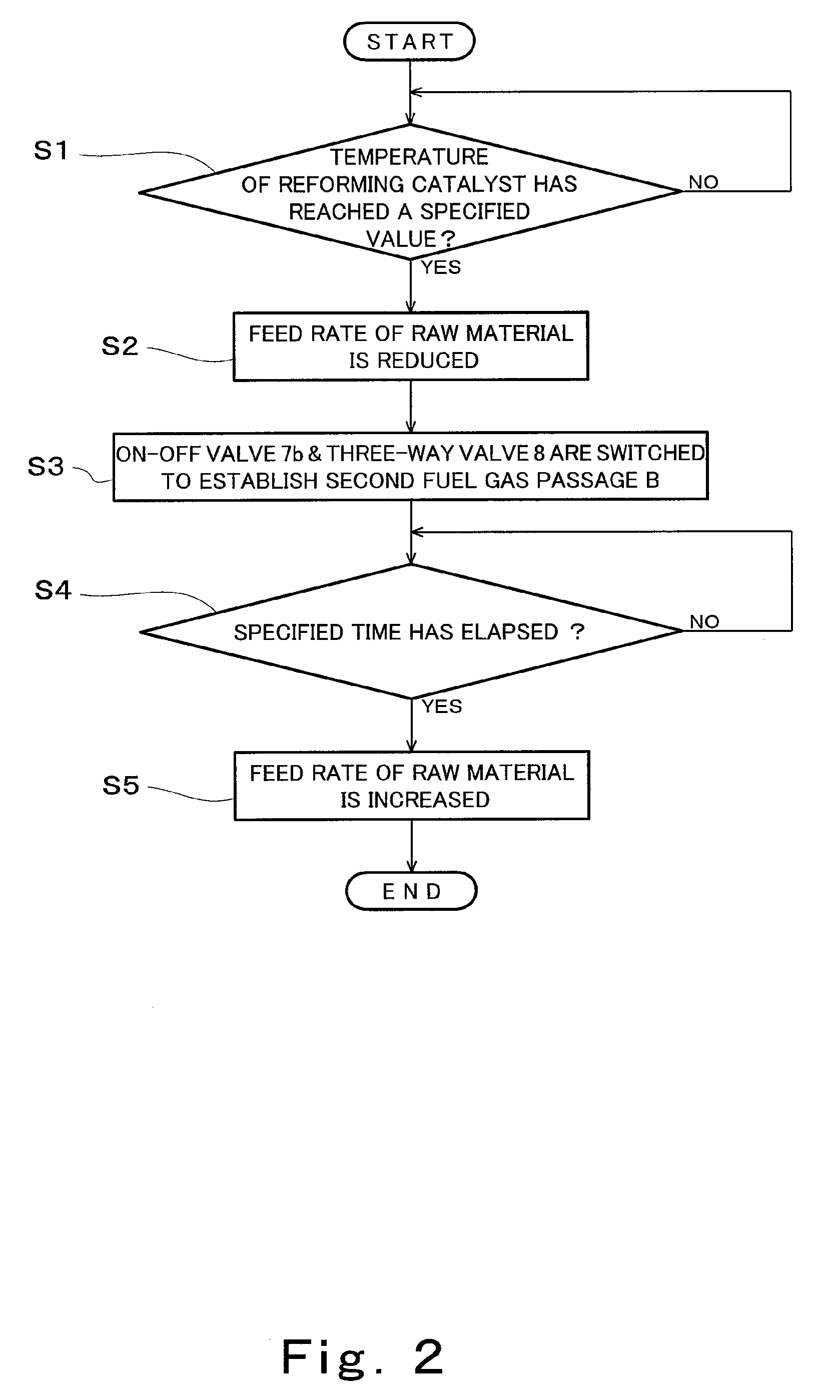
[0158]Instead of the patterns configured to simply reduce the feed rate of the raw material to the reformer 2 by the raw material feeder 10, the following pattern is preferably employed: When the three-way valve 8, which is the switching means of the invention, changes the destination of the fuel gas generated...


PUM

PropertyMeasurementUnit
electric poweraaaaaaaaaa
feed rateaaaaaaaaaa
concentrationaaaaaaaaaa

Abstract

A fuel cell system is provided, the system comprising: a fuel cell (1) configured to generate electric power by use of a fuel gas; a reformer (2) configured to generate the fuel gas by reforming a raw material; a combustion burner (2a) configured to supply heat for reforming; a raw material feeder (10) configured to control the feed rate of combustion fuel to the combustion burner; a combustion fan (2b) configured to supply air to the combustion burner; a fuel gas passage (R1, R4); an off gas passage (R3, R5); a bypass passage (R2); a switching valve (8); and a controller (101), wherein the inside of the fuel cell is filled with the raw material before the fuel gas is supplied, and wherein the controller controls the raw material feeder so as to reduce the feed rate of the combustion fuel to the combustion burner when controlling the switching valve so as to shut off the bypass passage to supply the fuel gas generated in the reformer to the fuel cell. This fuel cell system is environmentally-friendly and capable of suppressing the emission of carbon monoxide at the start of a power generating operation to mitigate the adverse effect upon the ecosystem.

Description

TECHNICAL FIELD[0001]The present invention relates to a fuel cell system for generating electric power by use of hydrogen and oxygen. More particularly, the present invention relates to a fuel cell system that utilizes the combustion heat of flammable material to generate hydrogen from raw material and uses this hydrogen for power generation.BACKGROUND ART[0002]In fuel cell systems capable of high-efficiency, small-scale power generation, it is easy to construct a system for utilizing heat energy generated during power generation. Thanks to this, fuel cell systems have heretofore been developed as a dispersed power generation system capable of achievement of high energy utilization efficiency.[0003]Fuel cell systems have fuel cell as the main body of the power generation section. The fuel cell directly converts the chemical energy of fuel gas and oxidizing gas into electric energy through a predetermined electrochemical reaction. Therefore, in the fuel cell systems, the fuel gas and...

Claims


Application Information

Patent Timeline
Patent Type & Authority Applications(United States)
IPC IPC(8): H01M8/04
CPCC01B3/323Y02B90/16C01B3/48C01B2203/0233C01B2203/0283C01B2203/044C01B2203/0445C01B2203/047C01B2203/066C01B2203/0811C01B2203/0822C01B2203/0827C01B2203/1223C01B2203/1235C01B2203/1241C01B2203/1604C01B2203/1609C01B2203/1685C01B2203/169C01B2203/1695H01M8/04022H01M8/04052H01M8/04223H01M8/04231H01M8/04268H01M8/04373H01M8/04753H01M8/04776H01M8/0612H01M8/0668H01M2250/405Y02E60/50C01B3/384H01M8/04225H01M8/04228Y02B90/10Y02P20/10
Inventor OZEKI, MASATAKANAKAMURA, AKINARIOHARA, HIDEO
Owner PANASONIC CORP
Why Eureka
Try Eureka