Capillary separated vaporization chamber and nozzle device and method

a vaporization chamber and nozzle technology, applied in the direction of isotope separation, separation process, electric discharge tube, etc., can solve the problems of confounded particle beam method, limited sensitivity, non-linear response, etc., and achieve the effect of improving electron ionization

Active Publication Date: 2009-04-23
AMIRAV AVIV
View PDF10 Cites 37 Cited by
  • Summary
  • Abstract
  • Description
  • Claims
  • Application Information

AI Technical Summary

Problems solved by technology

The particle beam method was, however, confounded with problems of limited sensitivity, non-linear response, ion source induced peak tailing and limited range of samples amenable for analysis in view of excessive sample degradation at the ion source.
In addition, standard electron ionization mass spectra suffer from a well-known “long felt need” of enhancing the relative abundance of the molecular ion which is missing or very weak in the EI mass spectra of about half of the particle beam LCL-MS sample compounds.
Without having a trustworthy molecular ion, sample identification with the library cannot be trusted, in view of possible interference from homologous and degradation compounds and the identification of samples that are not included in the library, is practically precluded.
This method of electron ionization LC-MS with SMB, however, suffers from a major problem (in addition to a few other problems) of poor robustness in view of too frequent clogging of the solvent delivery tube.
This problem of poor robustness is further exacerbated by the need to open the vacuum chamber each time that the clogged solvent delivery tube has to be serviced or replaced, followed by lengthy cycles of pump down and MS and ion source and optics tuning.
However, since with SMB all the added gas that is used for pneumatic assisted nebulization and spray formation is discharged into the vacuum, this mode of spray formation is considered as highly undesirable with SMB.
The use of thermally assisted spray that is also known as Thermospray, however, requires the heating of the sample solution at the solvent delivery tube, and this heating results in frequent solvent delivery tube clogging.
In addition, the output edge of the solvent delivery tube is unavoidably located inside the spray and sample vaporization tube, and this edge also suffers from a tendency to periodically clog.

Method used


Image

  • Capillary separated vaporization chamber and nozzle device and method
  • Capillary separated vaporization chamber and nozzle device and method
  • Capillary separated vaporization chamber and nozzle device and method

Examples


Embodiment Construction

[0026]In order to address the requirements above, eliminate the major adverse problem of solvent delivery tube clogging and improve the process of sample vaporization from a steady flow of liquid, one must eliminate or reduce the use of thermally assisted spray as much as possible and use alternative methods of spray formation for sample vaporization prior to its nozzle expansion. Preferably the spray should be achieved with minimal heat load on the solvent delivery tube.

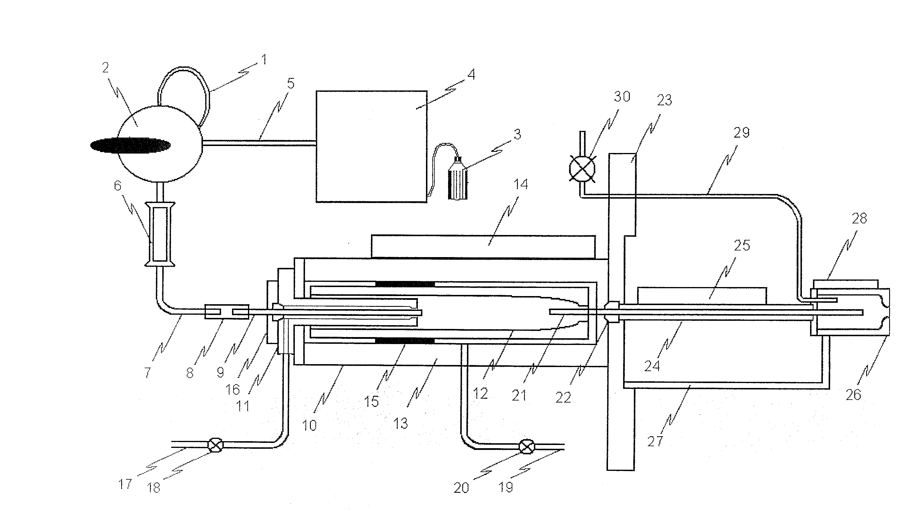
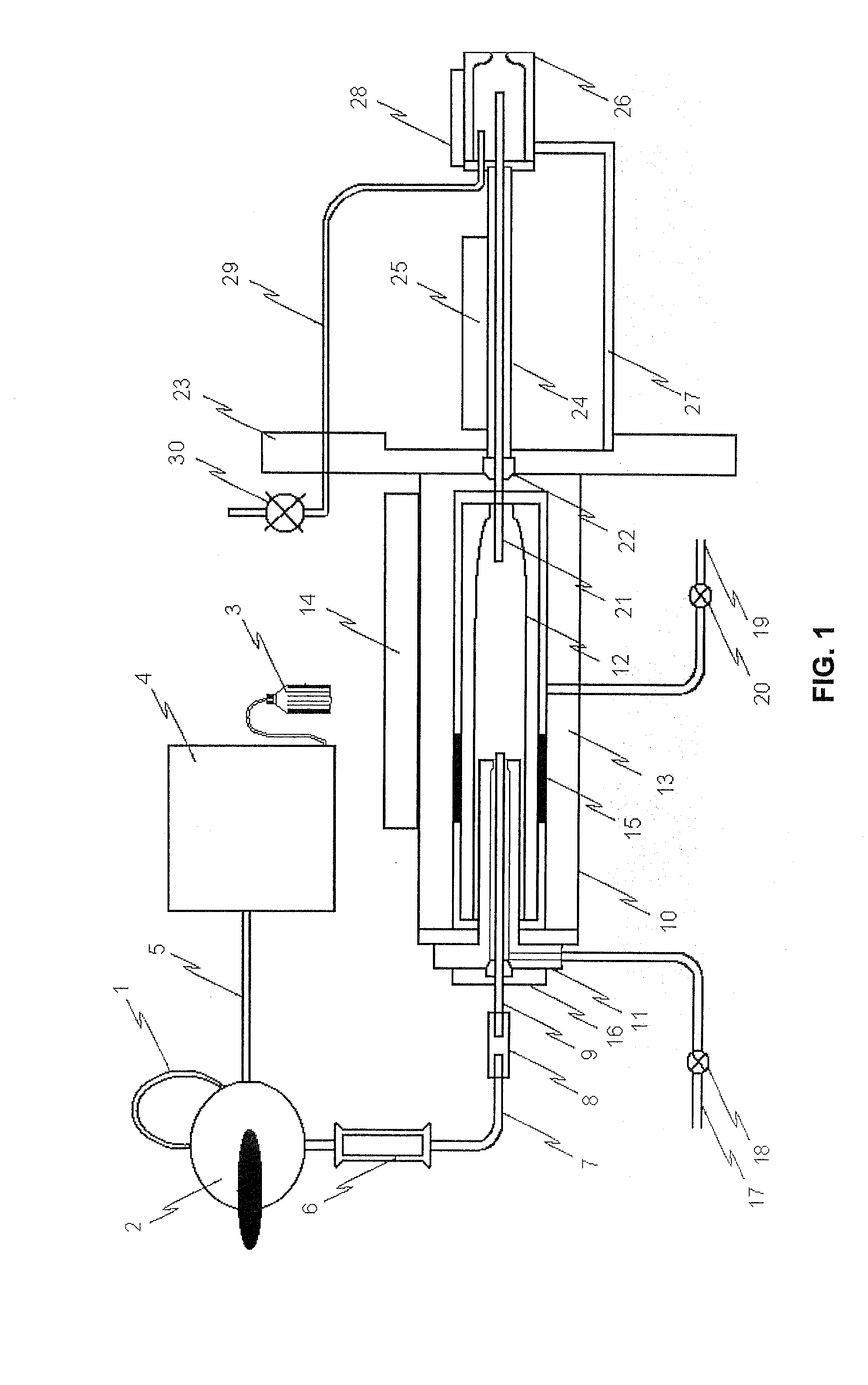
[0027]Illustrated in FIG. 1 is a schematic diagram of a capillary separated vaporization chamber and nozzle device according to the present invention. The sample is introduced into the sample loop 1 that is located on the flow injection valve 2. Solvent is pumped from the solvent container 3 by the LC pump 4 into solvent delivery tube 5 and sweeps the sample from its loop 1 into the LC column 6 for the separation of the sample compounds in time as normally achieved with LC analysis. The LC column 6 can be eliminated...


PUM


Abstract

There is provided a capillary separated vaporization chamber and nozzle method and device for improved electron ionization liquid chromatography mass spectrometry of samples in a supersonic molecular beam. The device includes a vaporization chamber located upstream of a supersonic nozzle; a capillary separating the vaporization chamber and the supersonic nozzle, means for spray formation from sample in a flowing liquid; a vacuum system into which the supersonic nozzle induces supersonic expansion of the vaporized sample compounds and solvent vapor, for forming a supersonic molecular beam with vibrationally cold sample molecules and vaporized solvent; flythrough electron ionization ion source; mass analyzer; an ion detector and means for data processing of the resulting mass spectral information, for identifying and / or quantifying the chemical content of the sample.

Description

FIELD OF THE INVENTION[0001]The present invention relates to a capillary separated vaporization chamber and nozzle method and device for improved electron ionization liquid chromatography mass spectrometry of samples in a supersonic molecular beam.BACKGROUND OF THE INVENTION[0002]Mass spectrometry (MS) is a central analytical technology that finds a large variety of applications in a broad range of fields, especially when coupled with a chromatographic separation technique such as gas chromatography (GC) or liquid chromatography (LC). Since a growing fraction of compounds that need to be analyzed are either thermally labile or with a low volatility (low volatiles), the use of LC-MS is growing recently at a faster rate than GC-MS. However, GC-MS still possesses a major advantage over LC-MS of having an automated sample identification through the use of extensive 70 eV electron ionization (EI) libraries.[0003]In the past, a method named particle beam was developed that enabled the com...

Claims


Application Information

Patent Timeline
Patent Type & Authority Applications(United States)
IPC IPC(8): B01D59/44
CPCH01J49/0431
Inventor AMIRAV, AVIV
Owner AMIRAV AVIV
Why Eureka
Try Eureka