Beam irradiation apparatus

a beam irradiation and apparatus technology, applied in the direction of reradiation, distance measurement, instruments, etc., can solve problems such as complex processing, and achieve the effect of simple computing process and proper detection

Inactive Publication Date: 2009-04-23
SANYO ELECTRIC CO LTD +1
View PDF1 Cites 12 Cited by
  • Summary
  • Abstract
  • Description
  • Claims
  • Application Information

AI Technical Summary

Benefits of technology

[0015]A first object of the present invention is to provide a beam irradiation apparatus capable of properly detecting a mirror turn position by a simple computing process. A second object of the present invention is to provide a beam irradiation apparatus capable of properly detecting a scan position of a laser beam in a target area.

Problems solved by technology

A problem occurs such that it makes the process complicated.

Method used


Image

  • Beam irradiation apparatus
  • Beam irradiation apparatus
  • Beam irradiation apparatus

Examples


first embodiment

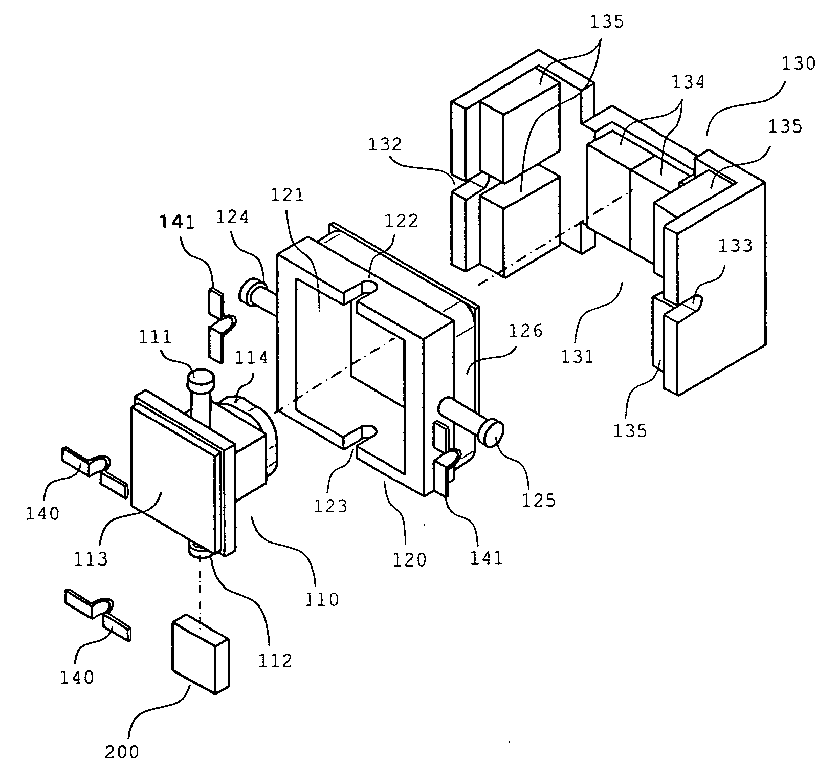
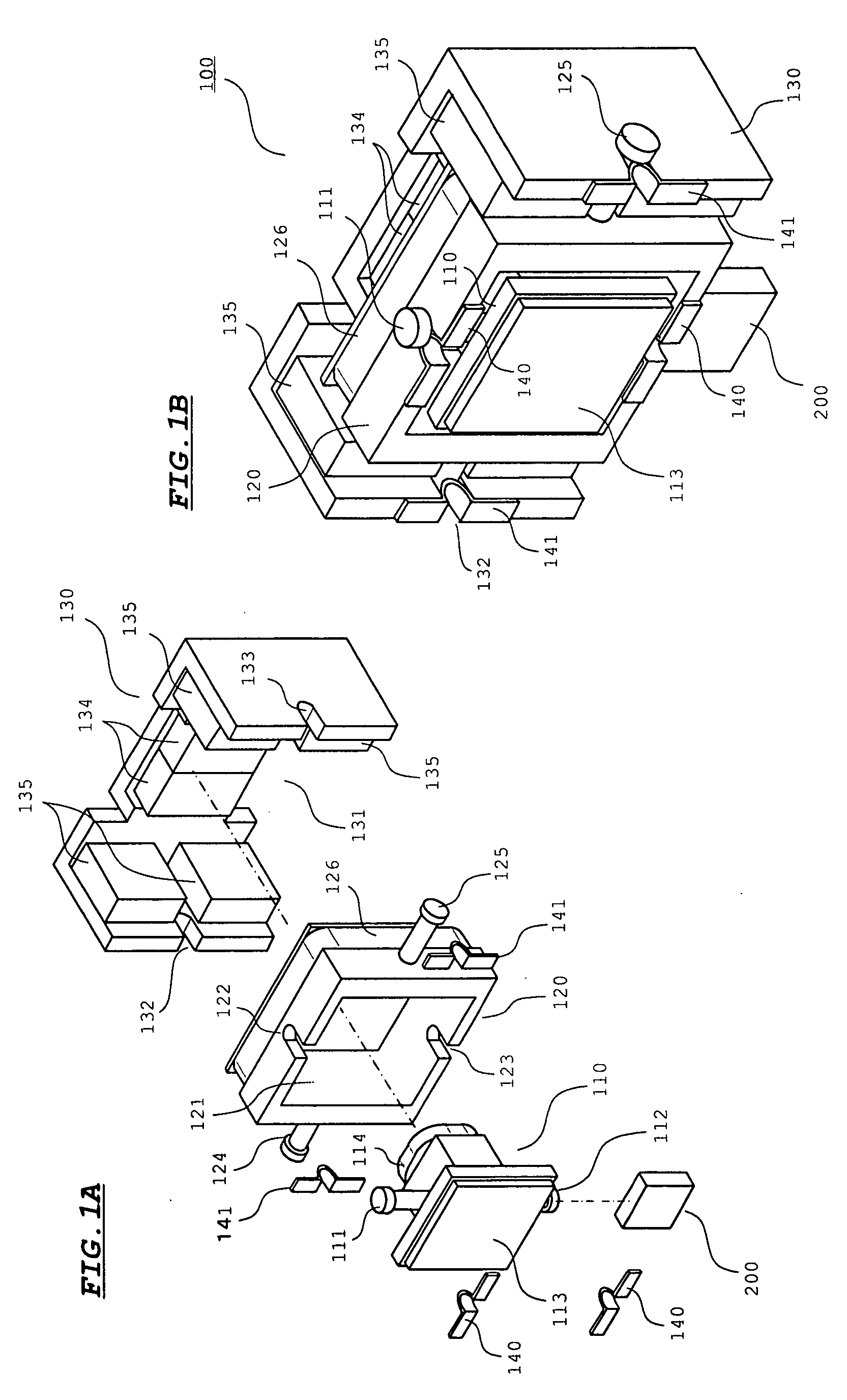
[0045]FIGS. 1A and 1B show the configuration of a mirror actuator 100 of a first embodiment. FIG. 1A is an exploded perspective view of the mirror actuator 100. FIG. 1B is a perspective view of the mirror actuator 100 in an assembled state.

[0046]In FIG. 1A, there is shown a mirror holder 110. In the mirror holder 110, spindles 111 and 112 each having a retainer at an end are formed. A plate-shaped mirror 113 is attached to the front face of the mirror holder 110, and a coil 114 is attached to the back face. The coil 114 is wound in a square shape.

[0047]A parallel-plate-shaped transparent member 200 is attached to the spindle 112. The transparent member 200 is attached to the spindle 112 so that two flat planes are parallel to mirror surfaces of the mirror 113.

[0048]A movable frame 120 supports the mirror holder 110 so that the mirror holder 110 can turn about the spindles 111 and 112 as axes. In the movable frame 120, an opening 121 for housing the mirror holder 110 is formed and gr...

second embodiment

[0101]The configuration of a mirror actuator in a second embodiment is the same as that shown in FIGS. 1A and 1B. The configuration of an optical system of a beam irradiation apparatus in the second embodiment is the same as that shown in FIGS. 2 and 3A except for the configuration of the transparent member 200.

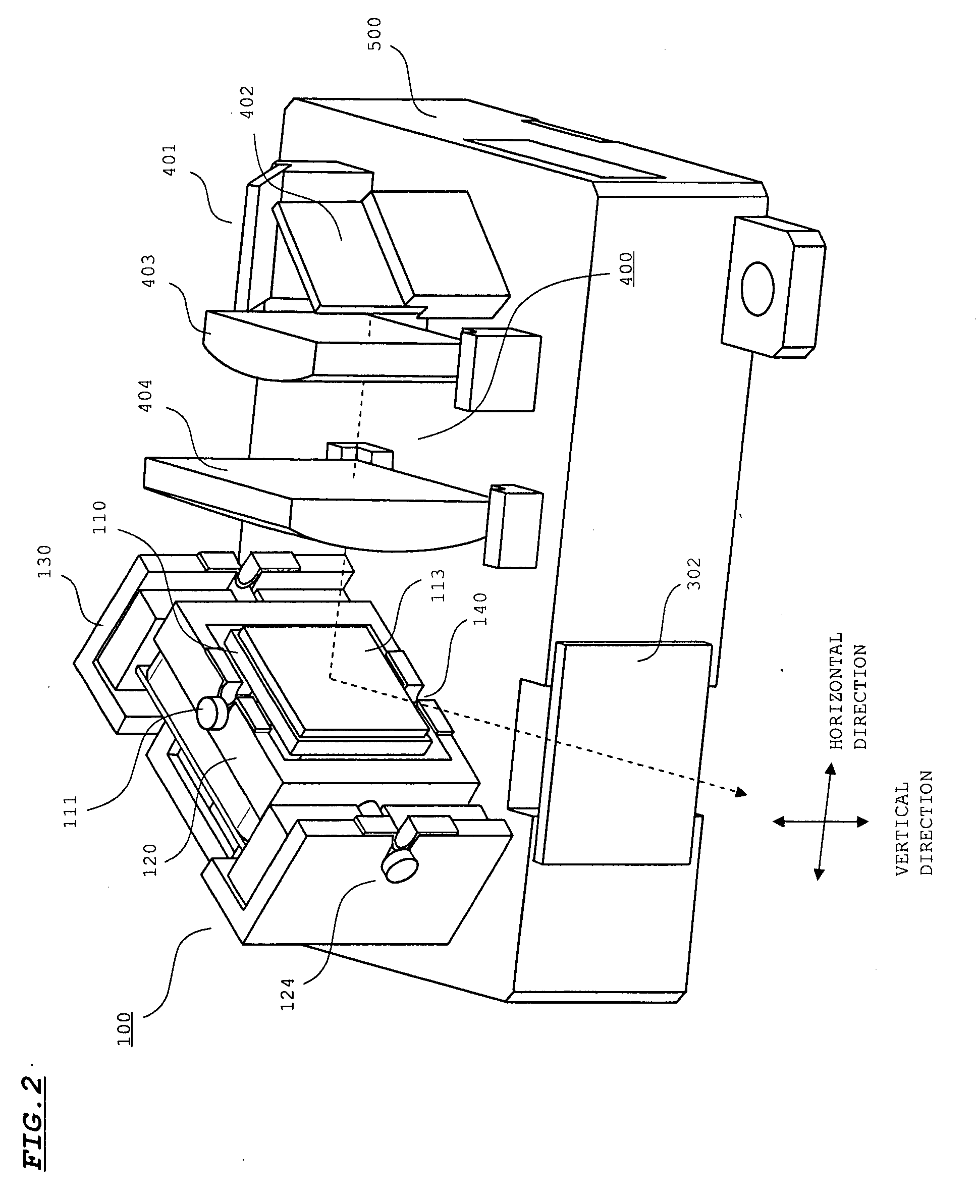
[0102]FIG. 13A is a partial plane view when the base 500 shown in FIG. 2 is seen from the back side. FIG. 13A shows a part around the position in which the mirror actuator 100 is attached in the back side of the base 500.

[0103]In the transparent member 200, as shown in FIG. 13B, fine periodic structures 201 are formed in the incidence plane and the outgoing plane of the servo beam. By the periodic structures 201, reflection of the servo beam in the incidence plane and the outgoing plane of the transparent member 200 is suppressed.

[0104]FIGS. 14A to 14C are diagrams schematically showing the periodic structure 201. FIGS. 14A, 14B, and 14C are a perspective view, a plane view, ...

example sample

c. Example Sample

[0129]material: polycarbonate (refractive index: 1.58)

[0130]thickness: 1 mm

[0131]incidence plane: a periodic structure having a pitch of nm and an aspect ratio of 1.52 is formed

[0132]outgoing plane: a periodic structure having a pitch of nm and an aspect ratio of 1.52 is formed

[0133]The periodic structure in the example sample was formed by a 2P mold using an ultraviolet curable resin (having a refractive index of 1.52). The output powers of the servo beam semiconductor laser for samples were set to the same.

[0134]FIG. 19 shows a measurement result. The abscissa axis indicates the angle θ in FIG. 18, and the longitudinal axis indicates a measurement value of transmission light intensity in a power meter. In the longitudinal axis, the measurement value when the angle θ was zero is shown as 1. In FIG. 19, “ARS (Anti Reflection Structure)” shows a result of measurement on the example sample, “PC panel” shows a result of measurement on the comparative example 1, and “AR...


PUM


Abstract

A laser beam and a servo beam are incident on a mirror and a transparent member, respectively, so that an angle direction A1 from an optical axis of the laser beam to be incident on the mirror to an incidence plane of the mirror and an angle direction A2 from an optical axis of the servo beam to be incident on the transparent member to an incidence plane of the transparent member are opposite to each other. With such layout of an optical system, scan loci of the servo beam corresponding to respective scan lines become closer to parallel. In the incidence plane and the outgoing plane of the servo beam of the transparent member, fine periodic structures tapered from the incidence plane and the outgoing plane are formed at pitches each equal to or less than a wavelength band of the servo beam. By this periodic structure, reflection of the servo beam on the incidence plane and the outgoing plane is suppressed.

Description

[0001]This application claims priority under 35 U.S.C. Section 119 of Japanese Patent Application No. 2007-247231 filed on Sep. 25, 2007, entitled “BEAM IRRADIATION APPARATUS”, and Japanese Patent Application No. 2007-239396 filed on Sep. 14, 2007, entitled “BEAM IRRADIATION APPARATUS”.1. FIELD OF THE INVENTION[0002]The present invention relates to a beam irradiation apparatus for irradiating a target area with a laser beam. More particularly, the present invention is suitable for use in a beam irradiation apparatus mounted on a so-called laser radar for detecting presence or absence of an obstacle in a target area and a distance to an obstacle based on reflection light when the a target area is irradiated with a laser beam.2. DESCRIPTION OF THE RELATED ART[0003]In recent years, to increase safety at the time of driving, a laser radar is mounted on a household passenger car or the like. The laser radar emits a laser beam to the front in the travel direction and detects presence or a...

Claims


Application Information

Patent Timeline
Patent Type & Authority Applications(United States)
IPC IPC(8): H01S3/10
CPCG01S3/784G01S7/4812G01S7/4813H01S5/005G01S17/42G01S17/936G02B26/101G01S7/4817G01S17/931
Inventor MAENO, YOSHIAKIYAMAGUCHI, ATSUSHI
Owner SANYO ELECTRIC CO LTD
Why Eureka
Try Eureka