
Electrohydraulic transmission controller, transmission device, and a motor vehicle drive train

Active Publication Date: 2009-04-30
ZF FRIEDRICHSHAFEN AG
View PDF6 Cites 11 Cited by
  • Summary
  • Abstract
  • Description
  • Claims
  • Application Information

AI Technical Summary

Benefits of technology

[0016]The electrohydraulic transmission controller of the invention represents a combination of a conventional transmission controller and a cooling oil system known from the state of the art, such that the thermal stress on a sub-assembly of a motor vehicle drive train can be reduced in a strategy-compatible manner. In contrast to the solutions known from the state of the art, with the electrohydraulic transmission control of the invention, thermal stress on a sub-assembly of a motor vehicle drive train can be more simply and cost-effectively reduced, because the cooling of a sub-assembly of a motor vehicle drive train that is under thermal stress can be carried out in a strategy-compatible manner, compared to a transmission controller known from the state of the art, with a transmission controller that is only marginally modified, without additional cooling devices. In addition, the idea of the invention can also be integrated into existing systems in a particularly simple manner and without elaborate constructive measures, and with minimal control and regulation complexity.
[0019]In this way, the transmission device of the invention combines the advantages of the electrohydraulic transmission controller with the advantage that, for reducing the thermal stress of the sub-assembly of a motor vehicle power train, the coolant circulation of the sub-assembly can be integrated in a simple way into the hydraulic circulation of the transmission device and the strategy-compatible cooling can consequently be implemented more economically.
[0021]With the motor vehicle drive train constructed in accordance with the invention, the thermal stress of a sub-assembly drive of a motor vehicle drive train can be reduced in a simple and cost-effective way. A cooling system of the sub-assembly that is preferably arranged externally to a transmission device is integrated into an electrohydraulic transmission controller of the transmission device in order to carry out cooling of the sub-assembly in a simple and cost-efficient manner. In addition, the motor vehicle drive train of the invention, in contrast to drive trains known from the state of the art, in which a sub-assembly configured with a switching element can be cooled in a strategy-compatible manner, can be manufactured in a more cost-efficient way and is characterized by less need for installation space and lower total weight.

Problems solved by technology

These stresses result from the greater frictional stresses on switching elements that are periodically operated in a slipping state during startup procedures or switching operations in the transmission device.
The different assemblies in hybrid motor vehicle drive trains are subjected to considerable thermal stresses during critical operating states because, particularly the switching elements between the internal combustion and electric engines and the transmission device must be transferred in a slipping state with high rotational speed differences and with high torque applying to them at the same time into an engaged operating state.
This results from the fact that in order to adequately cool the switching elements that are under great thermal stress, in addition to the hydraulic transmission systems, there must also be hydraulic cooling systems with their own coolant circulation and their own coolant pump, which exhibit complex construction, require a large installation space and have a high dead weight, and which are also characterized by a great control and regulation complexity which, among other things, results in high cost.

Method used


Image

  • Electrohydraulic transmission controller, transmission device, and a motor vehicle drive train
  • Electrohydraulic transmission controller, transmission device, and a motor vehicle drive train
  • Electrohydraulic transmission controller, transmission device, and a motor vehicle drive train

Examples


Embodiment Construction

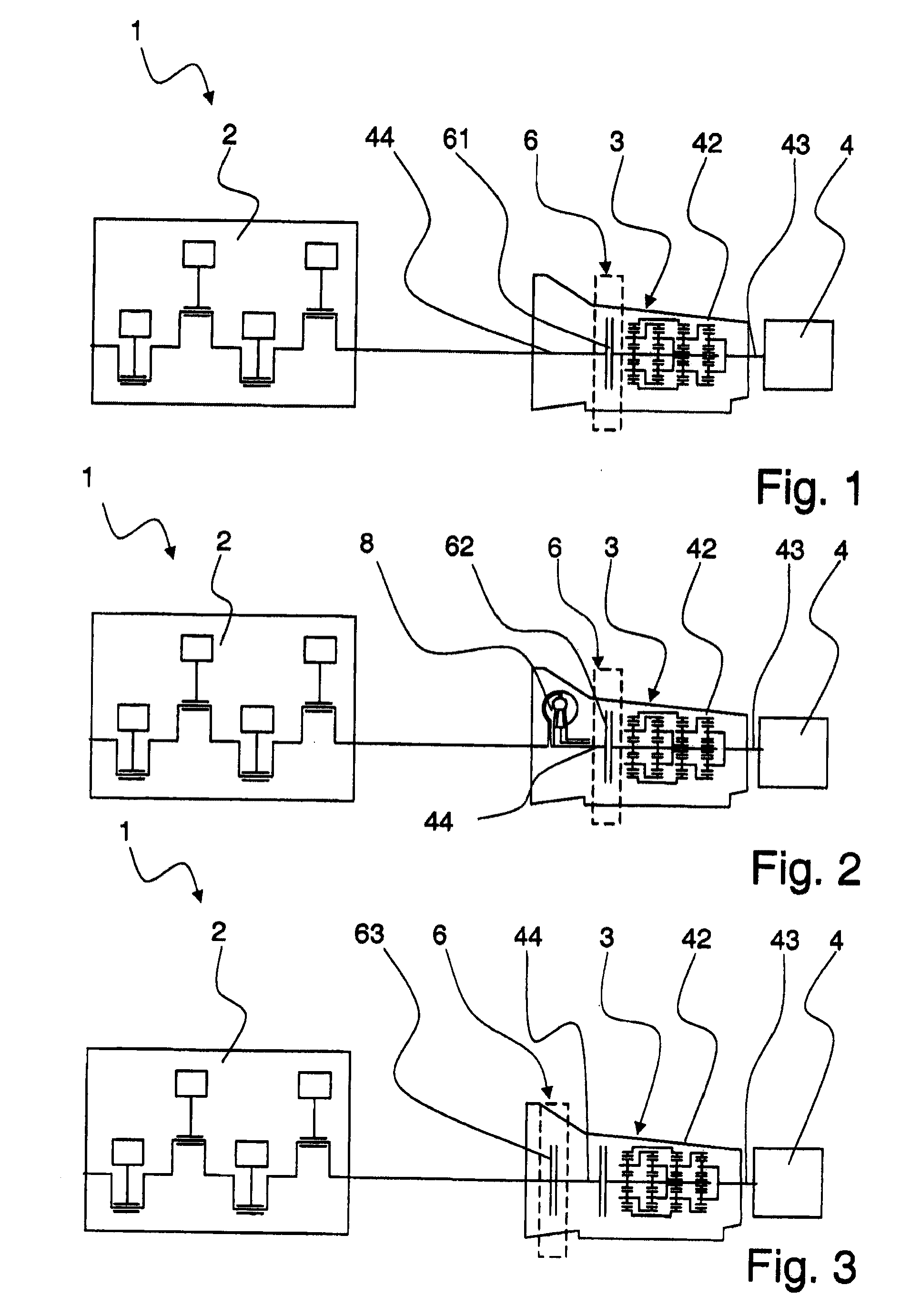
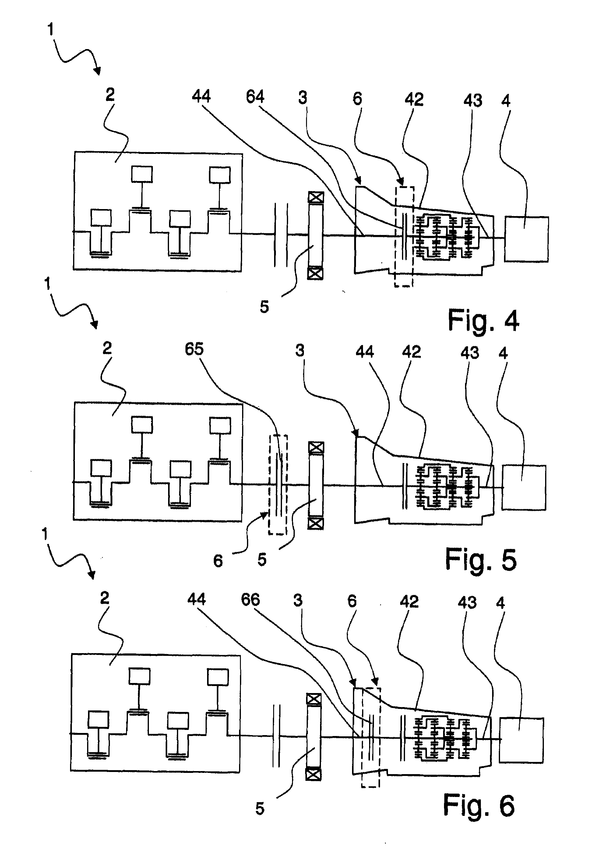
[0033]In FIG. 1 to FIG. 3, a plurality of embodiments are represented of a vehicle drive train 1 of a motor vehicle with an internal combustion engine 2, a transmission device 3, and an output 4. The vehicle drive trains according to FIG. 4 to FIG. 6 in addition to the previously cited main groups, are additionally configured in the area between the internal combustion engine 2 and the transmission device 3, with an electric engine 5 and, in each case, represent a parallel hybrid drive chain of a motor vehicle.

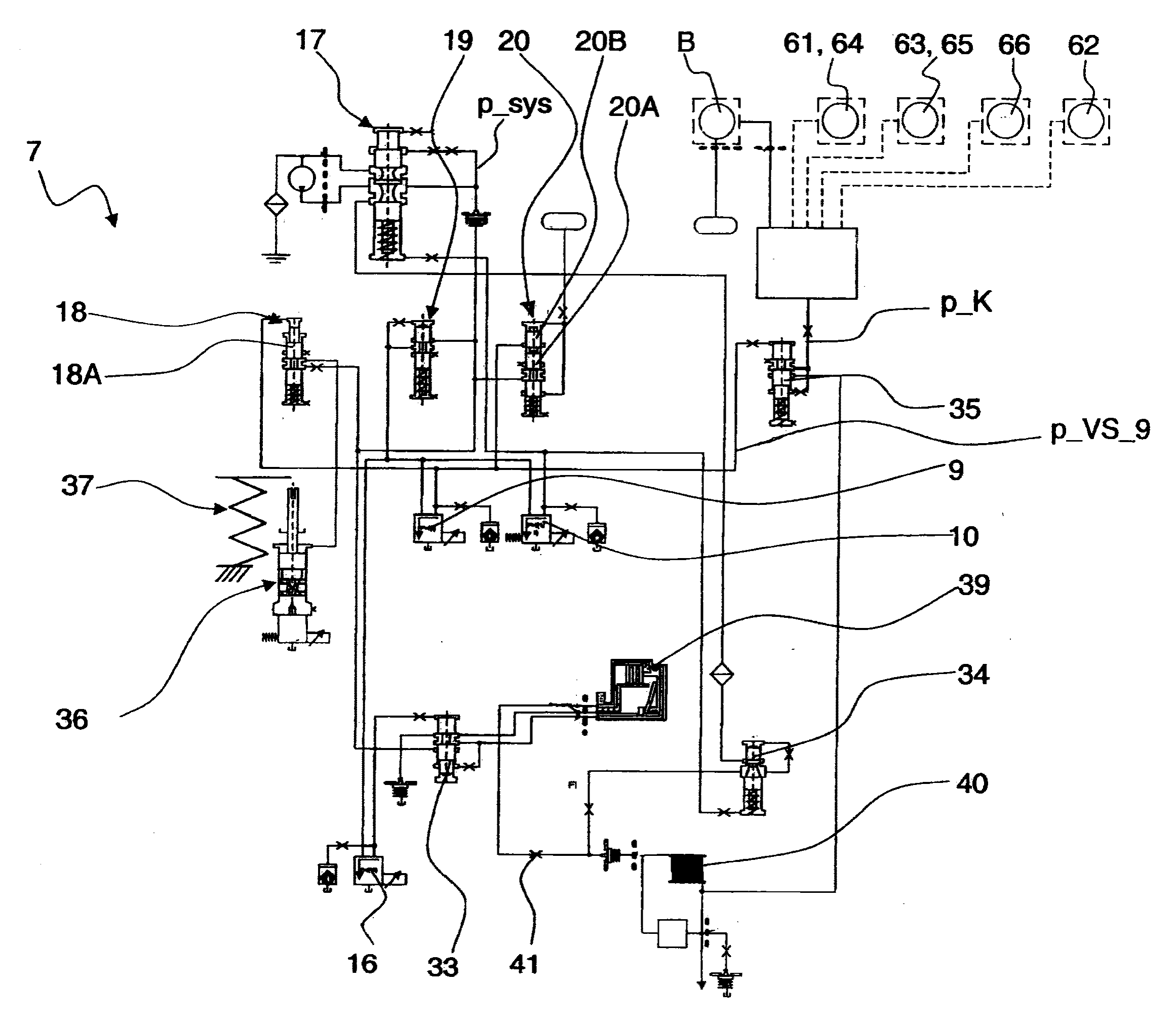
[0034]In addition, the vehicle drive trains 1 according to FIG. 1 to FIG. 6, in each case, are constructed with a sub-assembly 6, which is arranged inside or outside a transmission housing 42 and which, subject to the existing operating state at any given time of the vehicle drive train 1, can be acted on by way of a valve arrangement of an electrohydraulic transmission controller, shown in FIG. 7, FIG. 8 or FIG. 9, in a strategy-compatible manner, in the manner as described b...


PUM


Abstract

An electrohydraulic transmission controller (7), a transmission device with an electrohydraulic transmission controller and a vehicle drive train that features an electrohydraulic transmission controller are disclosed. The electrohydraulic transmission controller is constructed with a plurality of electrically actuatable pressure control valves (9 to 16), as well as with a plurality of valve arrangements (17 to 34) that can be acted on in each case by an hydraulic precontrol pressure depending upon the actuation of the pressure valves, by way of which valve arrangements switching elements (A to E) of a transmission device can be acted on in each case with a control pressure to produce a required operating state of the transmission device. An additional pressure control valve (9) is provided to adjust a precontrol pressure (p_VS—9) of an additional valve arrangement (35), whereby downstream of the additional valve arrangement, the sub-assembly (6) of a vehicle drive train can be acted on by a cooling oil volume flow subject to the precontrol pressure of the additional valve arrangement and an operating state of the additional valve arrangement (35) corresponding to it.

Description

[0001]This application claims priority from German Application Serial No. 10 2007 050 802.8 filed Oct. 24, 2007.FIELD OF THE INVENTION[0002]The invention relates to an electrohydraulic transmission controller with a plurality of electrically controlled pressure control valves, a transmission device of a motor vehicle drive train, as well as a vehicle drive train with a transmission device featuring an electrohydraulic transmission controller.BACKGROUND OF THE INVENTION[0003]In the motor vehicle drive trains known from the state of the art, which are equipped respectively with an internal combustion engine, a transmission device and an output. The component assemblies thereof are subjected to stresses depending on operating state. These stresses result from the greater frictional stresses on switching elements that are periodically operated in a slipping state during startup procedures or switching operations in the transmission device.[0004]In order to reduce fuel consumption and po...

Claims


Application Information

Patent Timeline
IPC IPC(8): F16H61/50F16K31/02
CPCF16H61/0021F16H61/0206F16H2061/0037F16H61/686F16H61/14F16H57/0473Y10T137/7761Y10T137/7762
Inventor GIERER, GEORGSCHMIDT, THILO
Owner ZF FRIEDRICHSHAFEN AG
Features
  • Generate Ideas
  • Intellectual Property
  • Life Sciences
  • Materials
  • Tech Scout
  • Unparalleled Data Quality
  • Higher Quality Content
  • 60% Fewer Hallucinations
Learn More