Arc Welding Initiation System and Method

a technology of arc welding and initiation system, which is applied in the direction of welding/cutting media/materials, welding apparatus, manufacturing tools, etc., can solve the problems of unstable arc at the start of the weld, affecting the entire weld, and fixed ratios of various gas components, so as to improve the quality of welds, reduce the amount of spatter, and ensure the arc initiation. high reliability

Active Publication Date: 2009-04-30
GM GLOBAL TECH OPERATIONS LLC
View PDF12 Cites 16 Cited by
  • Summary
  • Abstract
  • Description
  • Claims
  • Application Information

AI Technical Summary

Benefits of technology

[0007]An advantage of an embodiment is that, by controlling the gas mixture in real time in relation to arc initiation and at the end of the welding cycle, a high reliability of arc initiation will be achieved. With improved arc initiation, the amount of spatter is reduced, resulting in improved weld quality.
[0008]An advantage of an embodiment is that on-demand weld mode control is achieved, allowing a switch to and from a spray mode. This facilitates joint configuration and helps control spatter. Also, control over the shape of the welding wire tip at the end of the welding cycle is achieved.

Problems solved by technology

In either case, the ratios of various gas components are fixed, and so are not adjustable during the welding process even though the amount of penetration, the spatter generation, and the physical appearance are some of the attributes affected by the shielding gas mixture selected.
Moreover, instability of the arc at the start of the weld has a great affect on the entire weld since up to eighty percent of weld spatter may be generated at the time of arc start.
But this requires highly responsive, repeatable wire feeding mechanisms, which are not always built into arc welding systems.
If the wire feed for this technique is not smooth, it can cause arc initiation failure and excessive spatter generation.
But these methods require special operations that are not present in many arc welding systems.

Method used


Image

  • Arc Welding Initiation System and Method
  • Arc Welding Initiation System and Method
  • Arc Welding Initiation System and Method

Examples


Embodiment Construction

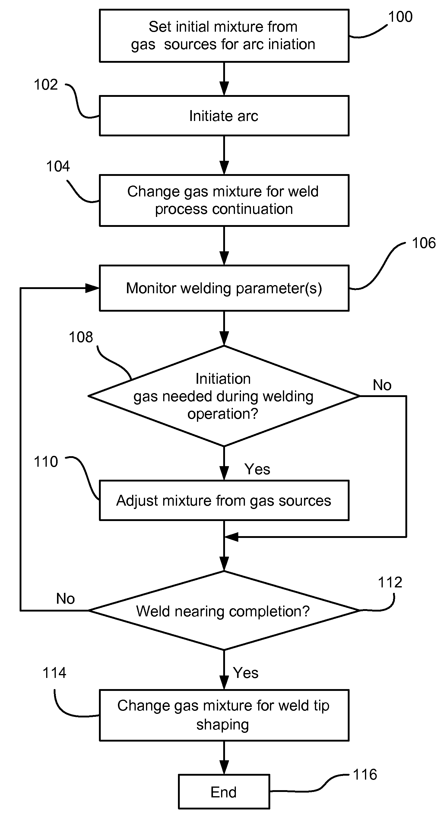
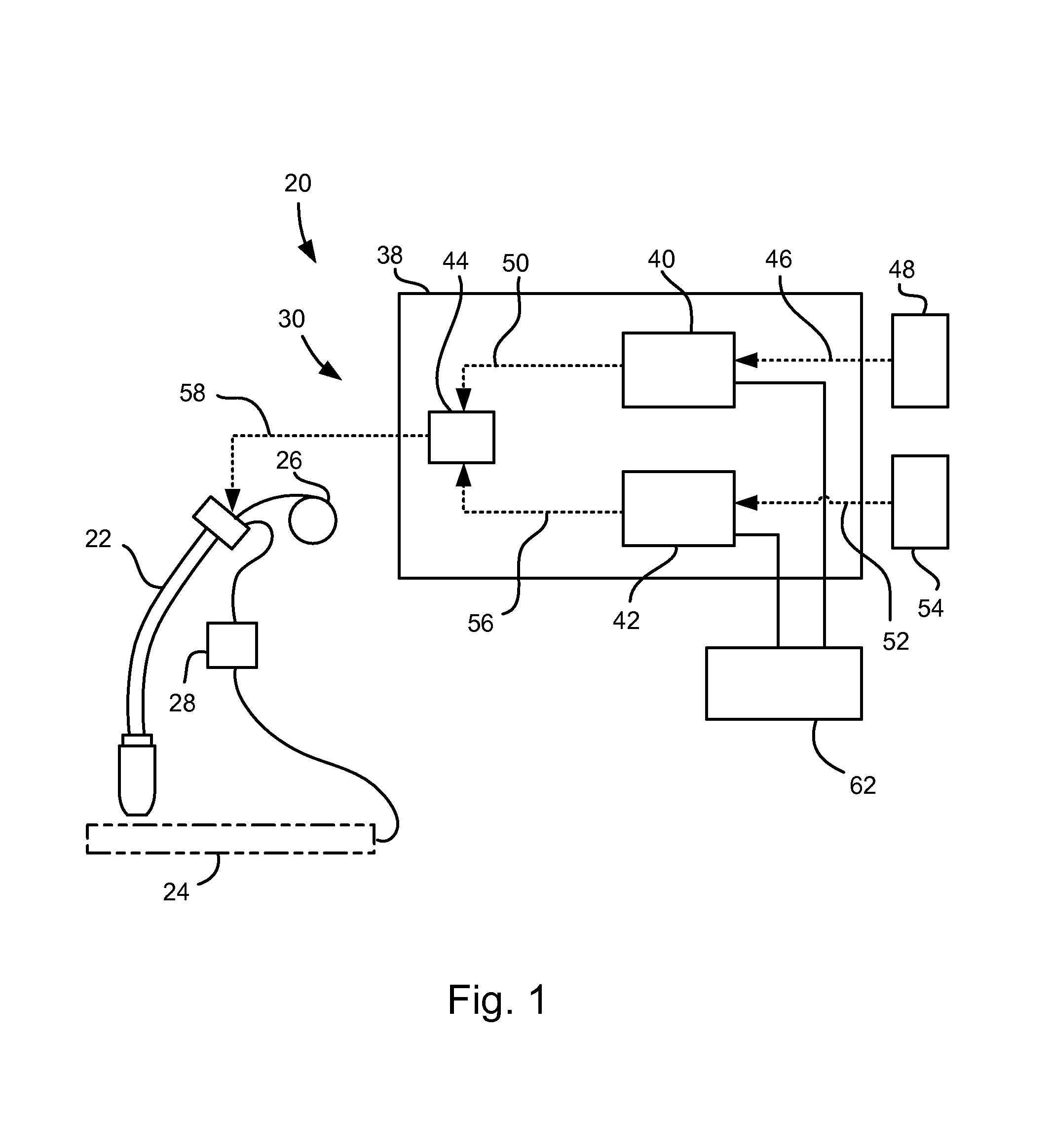
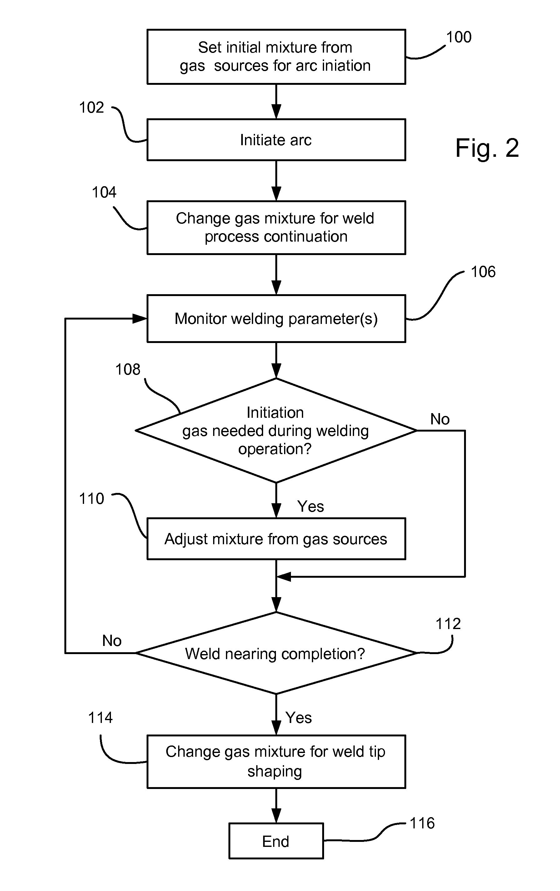
[0011]Referring to FIG. 1, an arc welding apparatus, indicated generally at 20, is shown. The arc welding apparatus 20 includes a weld gun 22 that is employed to perform a welding process upon a workpiece 24, a wire feed unit 26, an electric power source 28, and a shielding gas supply assembly 30.

[0012]The gas supply assembly 30 has a gas control unit 38 that includes a first valve 40, a second valve 42 and a mixing chamber 44. The first and second valves 40, 42 may be servo valves or other suitable types of automatically controllable valves for controlling the flow of the shielding gasses. The first valve 40 connects to a gas input line 46 extending from a first source of gas 48 and an output line 50 leading to the mixing chamber 44. Gas lines are indicated in FIG. 1 by dashed lines. The second valve 42 connects to a gas input line 52 extending from a second source of gas 54 and an output line 56 leading to the mixing chamber 44. A shielding gas supply line 58 extends from the mixi...


PUM

PropertyMeasurementUnit
stabilityaaaaaaaaaa
ionization potentialaaaaaaaaaa
weld stabilityaaaaaaaaaa

Abstract

A method and apparatus for controlling arc shielding gas during an arc welding operation is disclosed. The method may include the steps of actuating a first valve connected to an arc initiation source of gas to selectively allow arc initiation gas to flow through a mixing chamber; initiating an arc; actuating a second valve connected to a primary shielding source of gas to selectively allow primary shielding gas to flow through the mixing chamber; actuating the first valve to reduce, if needed, the arc initiation gas flow from the arc initiation source of gas; and continuing with the arc welding operation. The arc welding operation may also include actuating the first valve to cause the arc welding operation to operate in a different metal transfer mode when it is desirable, or when the arc welding operation is nearing completion.

Description

BACKGROUND OF INVENTION[0001]The present invention relates generally to arc welding applications.[0002]Some arc welding systems employ a wire and shielding (welding) gas fed through a welding gun. The shielding gas is directed into the welding zone while an electric current is passed through the arc between the electrode and the workpiece. The shielding gasses are used to improve the characteristics of the arc and protect the molten pool from ambient air oxidation. Stability of the arc can be significantly affected by the type of shielding gasses used. As a result, specific mixtures of shielding gasses are commonly used to improve the weld quality. The gas mixtures are supplied in pre-mixed tanks or in bulk systems employing a gas mixer. In either case, the ratios of various gas components are fixed, and so are not adjustable during the welding process even though the amount of penetration, the spatter generation, and the physical appearance are some of the attributes affected by th...

Claims


Application Information

Patent Timeline
Patent Type & Authority Applications(United States)
IPC IPC(8): B23K9/16B23K9/10
CPCB23K9/10
Inventor KHAKHALEV, ALEXANDER D.HAMPTON, JAY
Owner GM GLOBAL TECH OPERATIONS LLC
Why Eureka
Try Eureka