High dynamic range sensor with reduced line memory for color interpolation

Active Publication Date: 2009-04-30
OMNIVISION TECH INC
View PDF9 Cites 205 Cited by
  • Summary
  • Abstract
  • Description
  • Claims
  • Application Information

AI Technical Summary

Benefits of technology

[0009]An image sensor has an array of pixels organized into a row and column format that supports a line-by-line read out of the rows. The individual lines are buffered in a line image buffer of an image processor. Each pixel is also assigned a color filter array (CFA) filter according to a CFA pattern. An extended dynamic range is supported by selecting a sequence of column exposure times. An individual column of pixels has the same exposure time for all of the pixels within the column. However, the column exposure times are varied along a horizontal direction according to a periodic sequence. This results in an individual

Problems solved by technology

That is, an image sensor's total electrical dynamic range is limited by: 1) the charge saturation level at the upper end; and 2) the noise level at the lower end produced in the analog circuits and A/D conversion.
When the electrical dynamic range of an image sensor is too small to record all light intensity variations in a scene it will result in either the highlight portions being saturated or the shadowed parts

Method used


Image

  • High dynamic range sensor with reduced line memory for color interpolation
  • High dynamic range sensor with reduced line memory for color interpolation
  • High dynamic range sensor with reduced line memory for color interpolation

Examples


Example

[0017]Like reference numerals refer to corresponding parts throughout the several views of the drawings.

DETAILED DESCRIPTION OF THE INVENTION

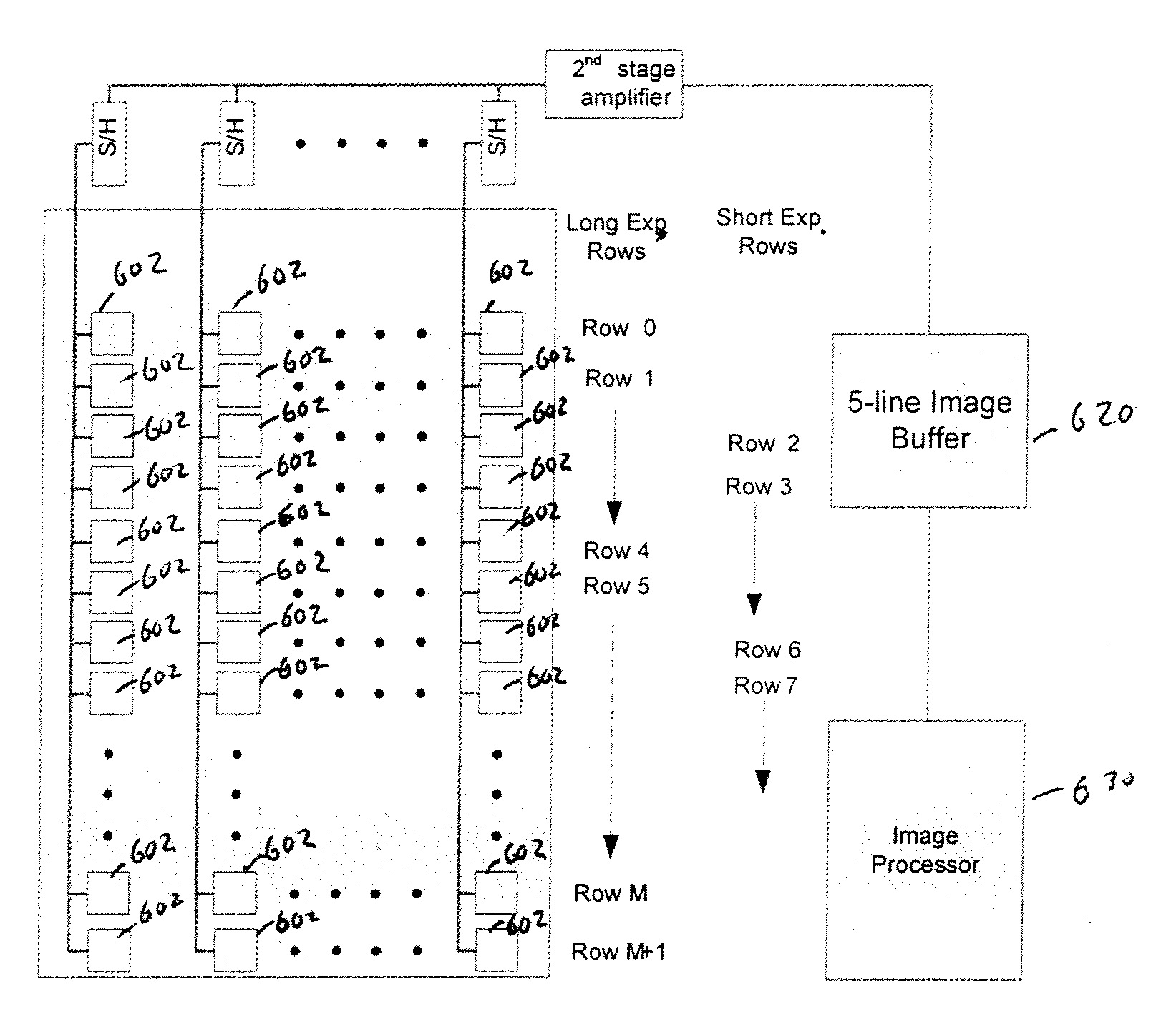
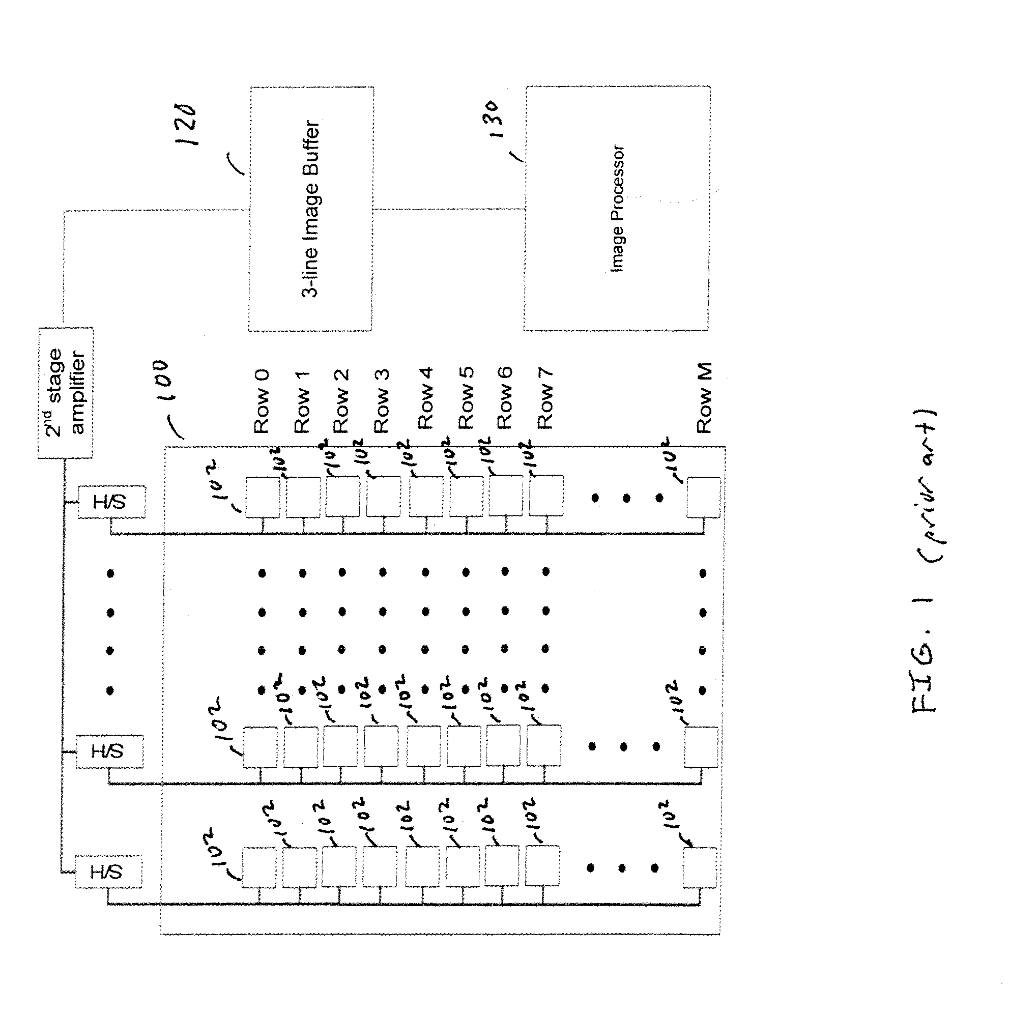
[0018]FIG. 3 illustrates an exemplary image sensing system in accordance with one embodiment of the present invention. A CMOS image sensor 300 includes a focal plane array 301 of pixels 302 (“a pixel array”). Each pixel 302 is a cell that includes a photo sensor (not shown) for producing a photo-generated charge in a doped region of the substrate. A conventional readout circuit (not shown) is provided for each pixel cell and includes at least a source follower transistor and a row select transistor for coupling the source follower transistor to a column output line. Sample and hold (S&H) elements 304 and amplifier 306 support the line-by-line read out of the rows. The pixel data is read out in a line-by-line basis and buffered in the line image buffer 320. In a preferred embodiment, the line image buffer is a 3-line image buffer 320 which has a...


PUM


Abstract

An image sensor has an array of pixels organized into a row and column format. Pixels are read out in a line-by-line sequence and buffered in a line image buffer. An extended dynamic range is supported by varying a column exposure time according to a periodic sequence. As a result, the pixel exposure times vary within each row. A high dynamic range is generated by combining pixel data of adjacent pixels within the same row that are of the same filter type but having different exposure times. Color interpolation is performed on the combined line data.

Description

FIELD OF THE INVENTION[0001]The present invention is generally related to the field of high dynamic range CMOS image sensor devices. More particularly the present invention is directed to techniques to perform color interpolation in a high dynamic range sensor.BACKGROUND OF THE INVENTION[0002]High dynamic range image sensors are desirable in a variety of application. As is well known in the field of image sensors, the dynamic range is the ratio of the largest detectable signal to the smallest (which for a CMOS image sensor is often defined by the ratio of the largest non-saturating signal to the standard deviation of the noise under dark conditions). That is, an image sensor's total electrical dynamic range is limited by: 1) the charge saturation level at the upper end; and 2) the noise level at the lower end produced in the analog circuits and A / D conversion. The light dynamic range of a scene is also defined as the ratio between the brightest and darkest objects that can be detect...

Claims


Application Information

Patent Timeline
IPC IPC(8): H04N5/335H04N9/04H04N5/235H04N1/46G03B7/00H04N3/14H04N9/083H04N5/347H04N5/355H04N5/376H04N9/07H04N9/64
CPCH04N5/235H04N5/347H04N5/3535H04N9/045H04N5/35545H04N5/35554H04N5/35572H04N5/35509H04N23/70H04N25/533H04N25/571H04N25/46H04N25/581H04N25/587H04N25/583H04N25/70H04N23/843H04N25/134
Inventor SHAN, JIZHANGKUANG, JIANGTAO
Owner OMNIVISION TECH INC
Why Eureka
Try Eureka