Three-pin integrated synchronous rectifier and a flyback synchronous rectifying circuit

a synchronous rectifier and integrated technology, applied in the direction of climate sustainability, dc-dc conversion, power conversion systems, etc., to achieve the effect of reducing costs and reducing the dimension of the print circuit board

Active Publication Date: 2009-04-30
NIKO SEMICON
View PDF6 Cites 79 Cited by
  • Summary
  • Abstract
  • Description
  • Claims
  • Application Information

AI Technical Summary

Benefits of technology

[0008]The characteristic of the present invention is that the quantity of the connection pins of the package and th

Problems solved by technology

Due to the package limitation, the synchronous rectifying circuit of the prior art is implemented by an expensive synchronous rectifyin

Method used


Image

  • Three-pin integrated synchronous rectifier and a flyback synchronous rectifying circuit
  • Three-pin integrated synchronous rectifier and a flyback synchronous rectifying circuit
  • Three-pin integrated synchronous rectifier and a flyback synchronous rectifying circuit

Examples


Embodiment Construction

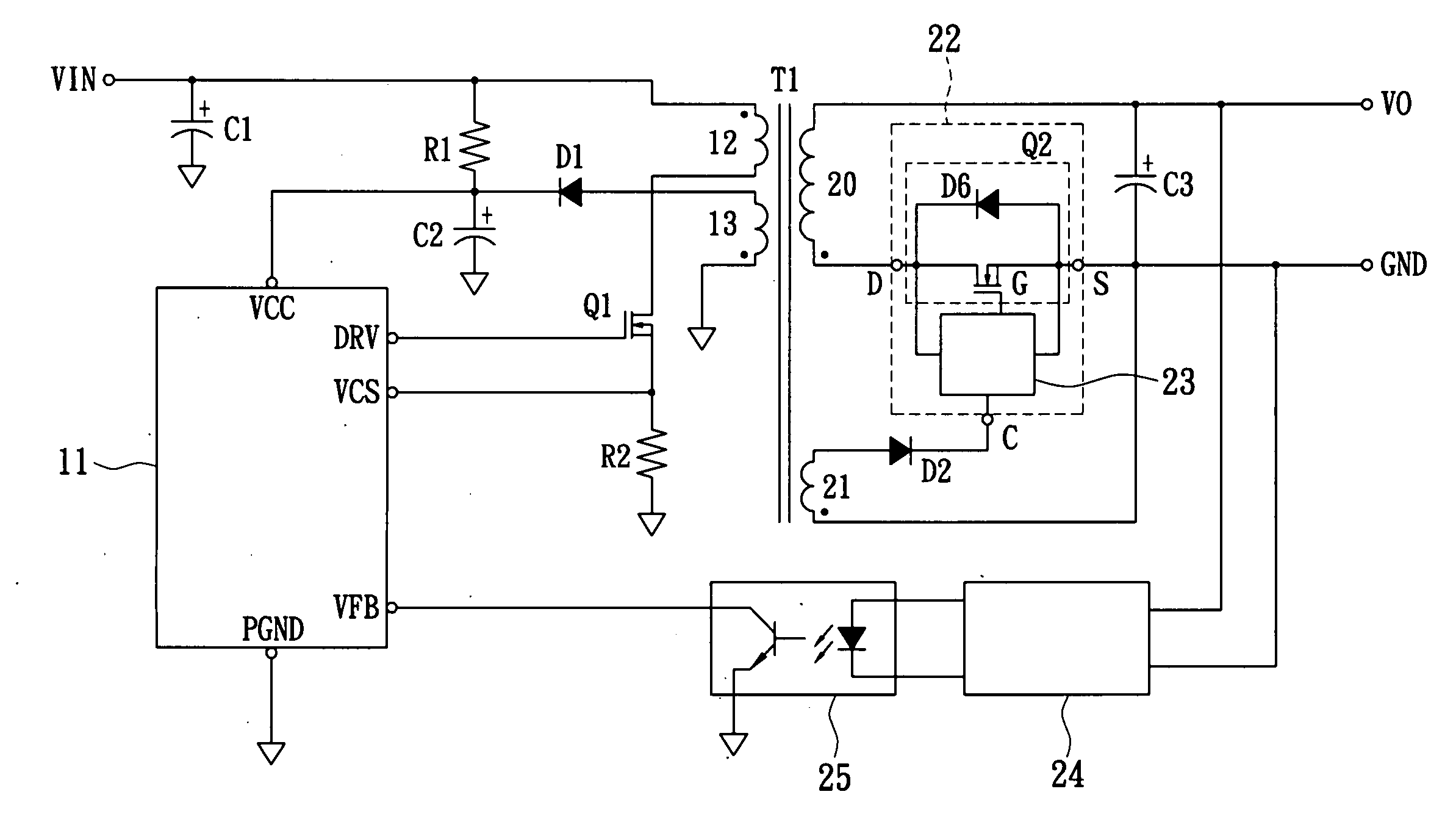
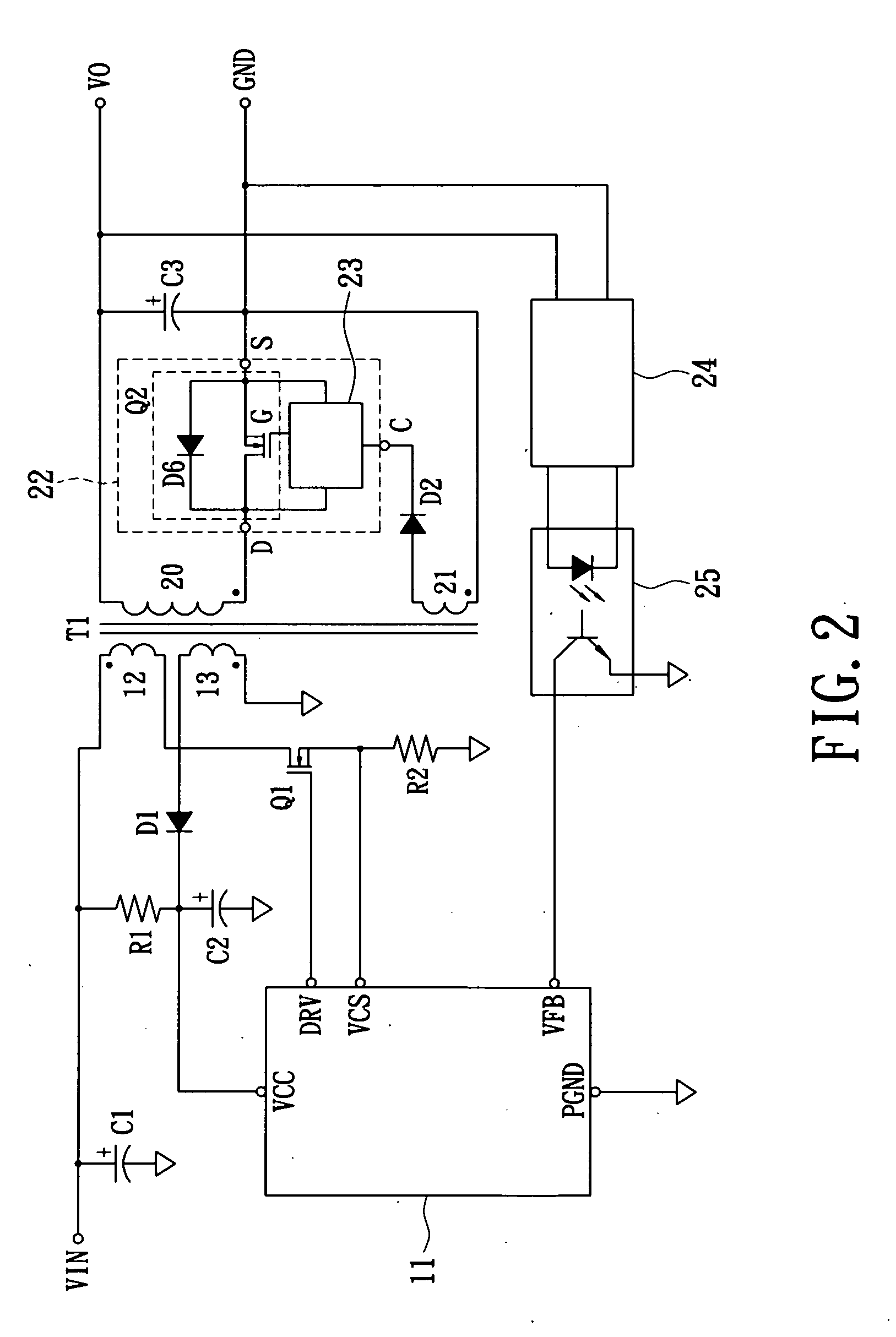
[0020]Reference is made to FIG. 2, which shows a circuit diagram of the three-pin integrated synchronous rectifier of the present invention applied to the flyback synchronous rectifying circuit. The circuit includes a DC power VIN, an input filtering capacitor C1, a turn-on resistor R1, a bias voltage power filtering capacitor C2, an output filtering capacitor C3, a primary PWM controller 11, a transformer T1 having a primary main winding 12, an primary auxiliary winding 13, a secondary output winding 20 and a secondary auxiliary winding 21, a rectifying diode D1 for providing a DC bias voltage power VCC, a primary side power transistor Q1 for controlling the power transmission of the transformer T1, a three-pin integrated synchronous rectifier 22, an output detection unit 24 (a feedback error-compensation amplifier in this embodiment), and an electrical isolation unit 25 (a photo coupler in this embodiment). When the power is turned on, the DC power VIN charges the bias voltage pow...


PUM


Abstract

A three-pin integrated synchronous rectifier is the synchronous rectifier chip where the quantity of connection pins is the smallest possible quantity. The three-pin integrated synchronous rectifier uses a control pin to receive a control signal used as a power bias voltage and a synchronous pulse to make the synchronous rectifier chip operate normally. The control signal is obtained from the output pin of an auxiliary winding via a diode. The other pins are respectively the drain pin and the source pin of an internal power transistor and are connected with the output winding and the voltage output terminal for transmitting the power of the transformer to supply current for the loading.

Description

BACKGROUND OF THE INVENTION[0001]1. Field of the Invention[0002]The present invention relates to a three-pin integrated synchronous rectifier and a flyback synchronous rectifying circuit that utilize a control pin to provide a control signal, whereby the control signal is used as a power bias voltage and a synchronizing signal, and a power transistor is built in a single package so that the connection pins are reduced. The structure is simplified so that the required area on the print circuit board is reduced and the cost of the power supply is decreased.[0003]2. Description of the Related Art[0004]The switching power supply traditionally is implemented by a diode rectifier. In order to meet the requirements, such as environmental protection, cooling and power efficiency, the diode rectifier gradually is replaced by the synchronous rectifier. However, the synchronous rectifying circuit of the prior art has a structure in which the control circuit and the power transistor are separat...

Claims


Application Information

Patent Timeline
IPC IPC(8): H02M3/335
CPCY02B70/1475H02M3/33592Y02B70/10
Inventor HSU, TA-CHING
Owner NIKO SEMICON
Why Eureka
Try Eureka