Mobile soil mapping system for collecting soil reflectance measurements

a technology of reflectance measurement and mobile soil, which is applied in the field of collecting and standardizing soil reflectance data, can solve the problems of difficult to accurately and affordably map soil properties within a field, difficult to measure changes in soil carbon levels, and impractical sampling density needed to capture small spatial scale variability using conventional sampling and analysis methods

Inactive Publication Date: 2009-04-30
VERIS TECH
View PDF18 Cites 80 Cited by
  • Summary
  • Abstract
  • Description
  • Claims
  • Application Information

AI Technical Summary

Benefits of technology

[0015]According to another aspect of the present invention, a method of collecting standardized soil reflectance data is provided, comprising: providing an implement for traversing a field to be mapped and a reflectance module carried by the implement for collecting spectroscopic measurements of soil in the field, the reflectance module having a light source and an optical receiver

Problems solved by technology

Accurately and affordably mapping soil properties within a field has proven challenging for soil scientists and precision agriculture practitioners.
The sampling density needed to capture small spatial scale variability is impractical using conventional sampling and analysis methods.
One of the challenges soon to be facing agricultural soil measurements involves accurately identifying soil carbon sequestration levels.
What makes measuring changes in soil carbon levels challenging is the expected carbon increase is small relative to the amount of carbon variabili

Method used


Image

  • Mobile soil mapping system for collecting soil reflectance measurements
  • Mobile soil mapping system for collecting soil reflectance measurements
  • Mobile soil mapping system for collecting soil reflectance measurements

Examples


Embodiment Construction

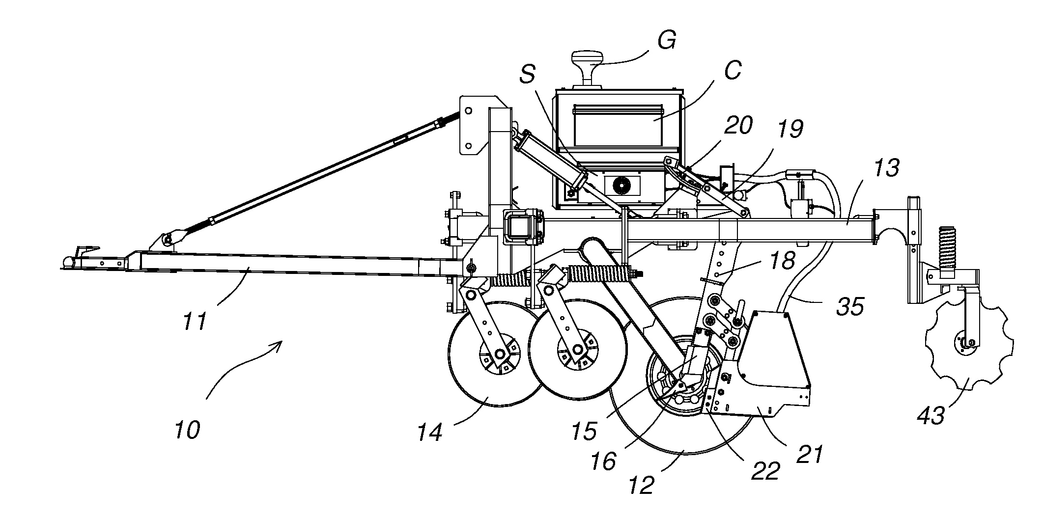
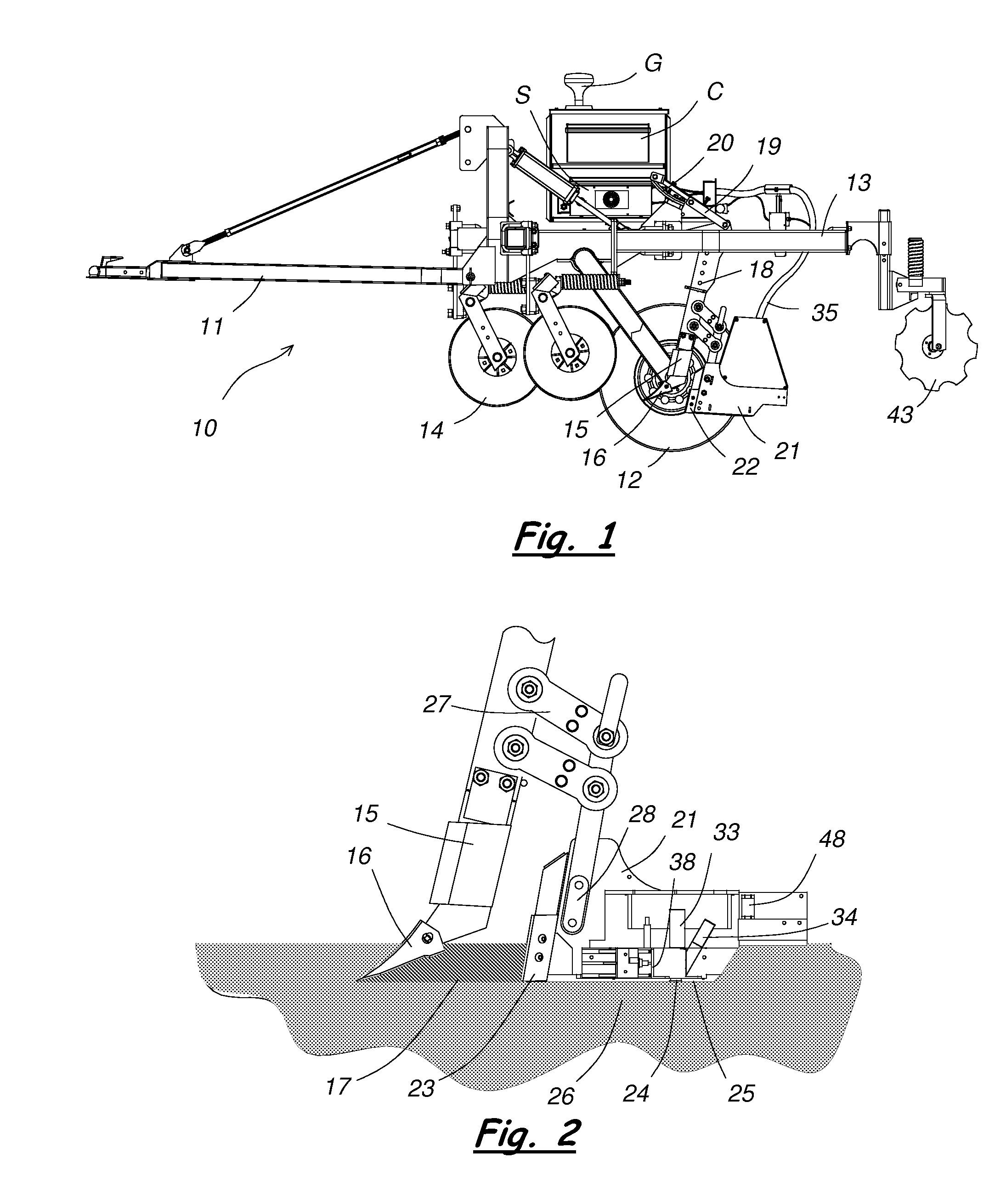
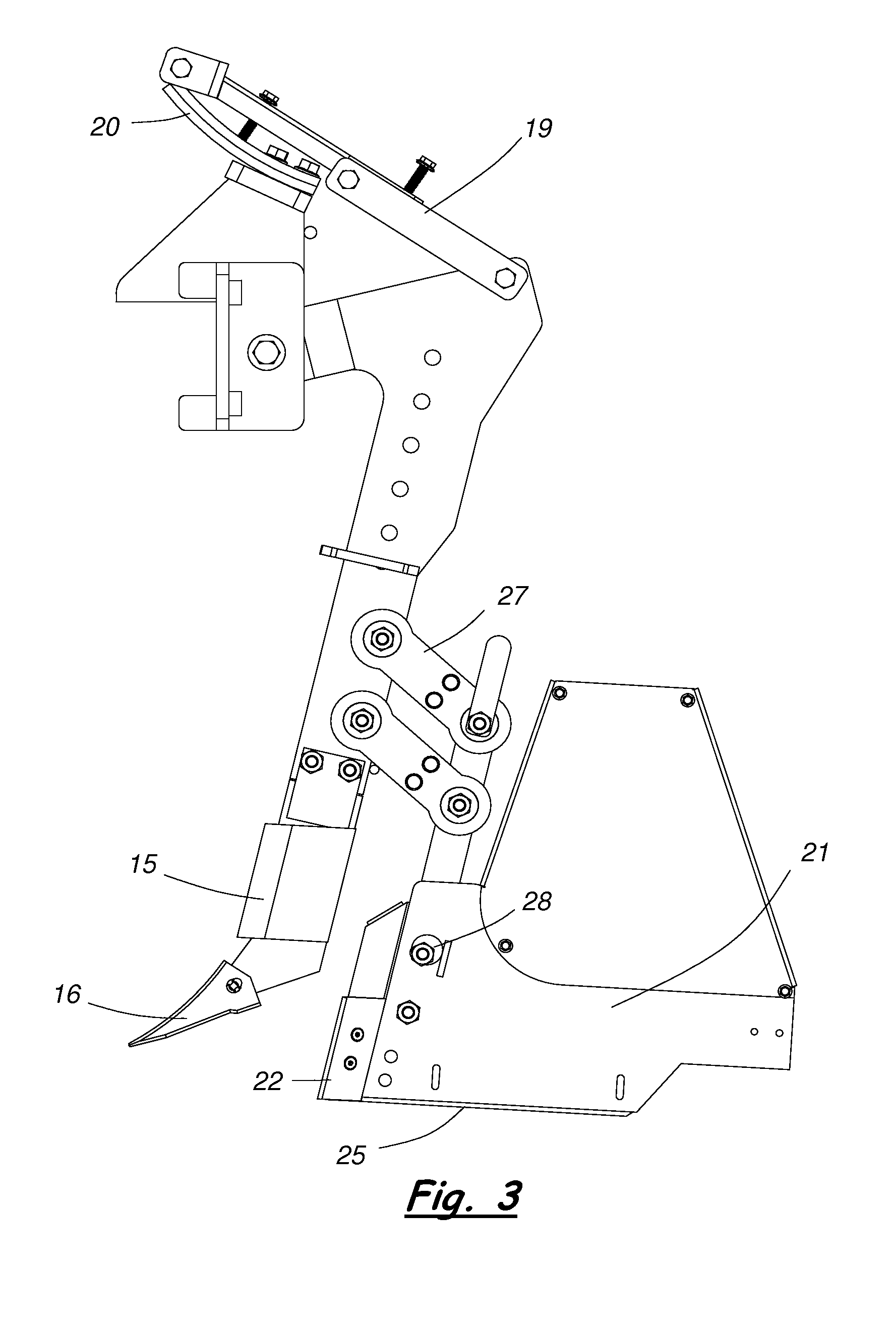
[0033]A mobile soil mapping system for collecting on-the-go reflectance measurements of soil in a field according to the present invention will now be described in detail with reference to FIGS. 1 to 16 of the accompanying drawings.

[0034]The soil mapping system is used to measure diffuse reflectance of soil at sampled locations while traveling through the field. The system includes an implement 10 for traversing a field to be mapped, a GPS receiver G to geo-reference all data collected, a portable computer C to process and record data, a spectrometer S to measure diffuse light reflectance, and various other components mounted on and carried by the implement. The implement 10 includes a draw bar 11 for connecting to a towing vehicle, a set of support wheels 12 that can be vertically adjusted to raise and lower the implement relative to the soil, and a frame 13 on which the various other components are mounted.

[0035]A fluted coulter 14 is connected to the implement 10 near the front o...


PUM


Abstract

A mobile soil mapping system includes an implement for traversing a field to be mapped, and a reflectance module carried by the implement for collecting spectroscopic measurements of soil in the field. The reflectance module has a light source, an optical receiver for transmitting light to a spectrometer, and a shutter system that alters the optical path between the light source and the optical receiver. The shutter system allows the system to automatically collect a dark reference measurement and a known reference material measurement at timed intervals to compensate for drift of the spectrometer and the light source. A self-cleaning window on the reflectance module has a lower surface maintained in firm contact with the soil during operation. External reference blocks are used to calibrate the system to ensure standardized, repeatable data. Additional sensors are carried by the implement to collect other soil data, such as electrical conductivity and temperature.

Description

RELATED APPLICATIONS[0001]This application claims priority of U.S. Provisional Application No. 60 / 982,395 filed on Oct. 24, 2007. The content of this prior application is incorporated herein by reference.BACKGROUND OF THE INVENTION[0002]1. Field of the Invention[0003]The present invention relates generally to methods and devices for analyzing and mapping soil properties within a field. In particular, the present invention relates to methods and devices for collecting and standardizing soil reflectance data.[0004]2. Description of the Related Art[0005]Accurately and affordably mapping soil properties within a field has proven challenging for soil scientists and precision agriculture practitioners. The sampling density needed to capture small spatial scale variability is impractical using conventional sampling and analysis methods. One of the challenges soon to be facing agricultural soil measurements involves accurately identifying soil carbon sequestration levels. This arises out of...

Claims


Application Information

Patent Timeline
IPC IPC(8): G01V3/38
CPCA01B79/005G01N21/15G01V8/02G01N21/3563G01N21/359G01N21/276A01C21/007
Inventor CHRISTY, COLINDRUMMOND, PAUL
Owner VERIS TECH
Why Eureka
Try Eureka