
Gravity Power Generation Mechanism

a gravity power generation and gravity technology, applied in mechanical energy handling, mechanical equipment, machines/engines, etc., can solve the problems of insufficient energy sources which can adequately produce energy, air pollution and the global greenhouse effect, and the amount of fossil fuels in the earth's crust is decreasing rapidly, so as to achieve effective and stable energy output, continuous and stable operation, and long-term

Inactive Publication Date: 2009-05-07
WANG CHUN CHAO +1
View PDF5 Cites 30 Cited by
  • Summary
  • Abstract
  • Description
  • Claims
  • Application Information

AI Technical Summary

Benefits of technology

[0009]The primary objective of the present invention is to provide gravity power generation mechanism which can provide a continuous and stable operation to continuously convert the gravity potential energy into the kinetic energy and then to convert the kinetic energy into the electric energy, so as to perform a long-time, effective and stable energy output.
[0011]By such arrangements, the gravity power generation mechanism not only has the advantages, such as: more simplified in structure, higher conversion ratio, and more environment-friendly but only needs a little of starting energy to perform a long-time energy conversion. More particularly, the gravity is more stable, so the present invention is more stable than the wind power generation and the solar power generation systems and can be placed at an arbitrary position without being affected by the outside environment.
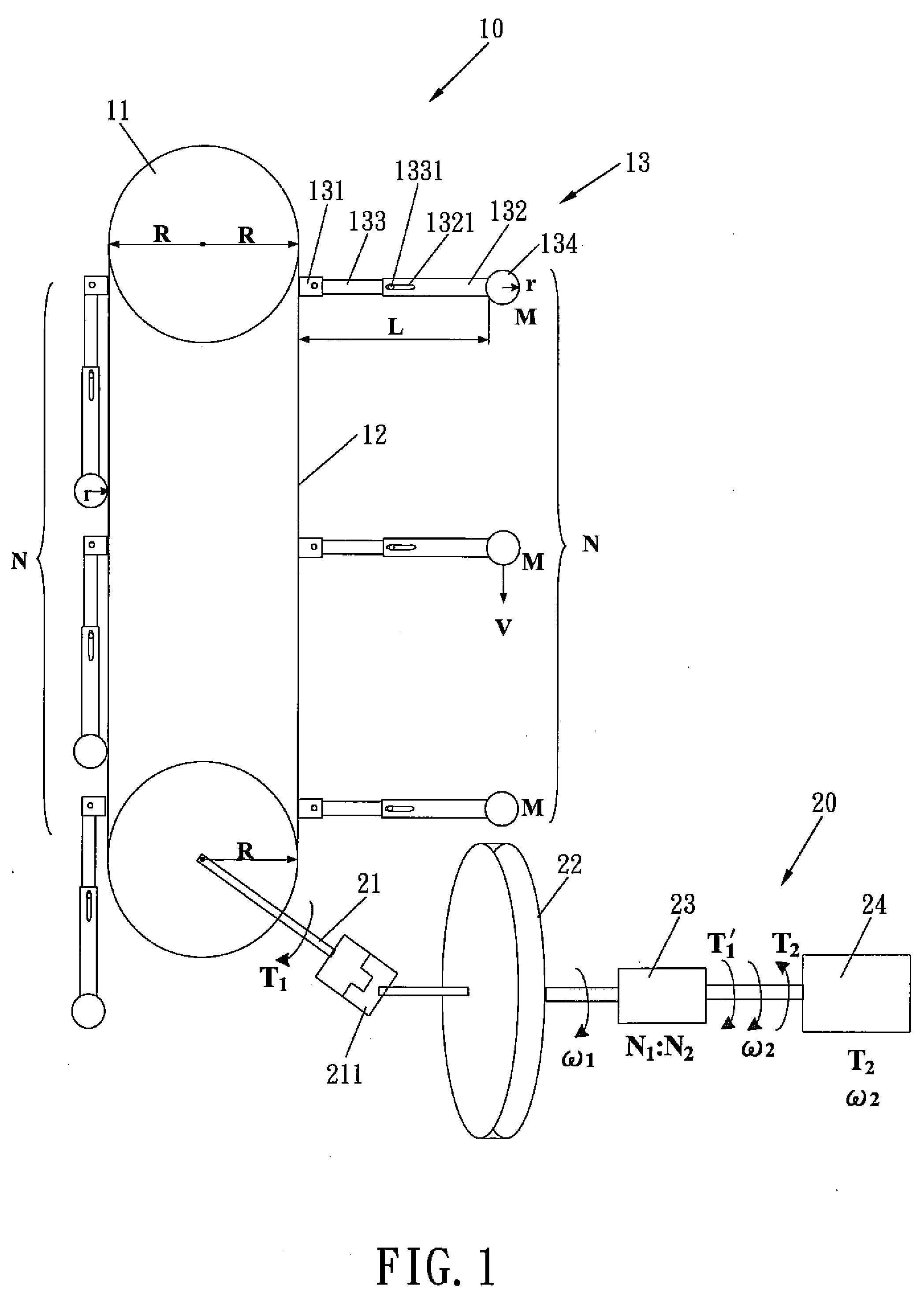
[0013]The gravity power generation mechanism of the present invention utilizes a gravity energy conversion unit to convert the gravity potential energy into the kinetic energy, performing a long-time, effective and stable energy output. The gravity power generation mechanism of the present invention not only can independently generate electricity but can be parallel connected to the wind power and the solar power generation systems to generate electricity. By such arrangements, after the motor is started to provide the gravity power generation mechanism a little of starting energy, the gravity power generation mechanism can self-output the energy for a long time.
[0015]The single directional pivot seats only allow the respective single directional swing arms to be pivotally folded 90 degrees in opposite direction of the transmitting member, and the respective single directional swing arms can freely rotate within a horizontal and vertical angle with respect to the transmitting member.

Problems solved by technology

Recently, the energy source which can adequately produce energy is insufficient, and this has become an urgent problem to be solved for every country.
However, the burning of fossil fuel will cause the air pollution and the global greenhouse effect.
In addition, due to the high consumption of the fossil fuel, the amount of fossil fuel in the earth's crust is decreasing rapidly.
Though the nuclear energy is always available for use by nuclear fission and nuclear fusion, the safety of the nuclear power plant is still controversial.
It is important that, how to correctly treat the nuclear waste material has become a puzzled problem for human beings.
The storage and the accumulation of the waste material are both costly and difficult to perform.
Other energy sources, such as solar energy, wind energy and tidal energy, are the non-pollution energy sources which the modern people seek for, but they are the natural energy which the human beings cannot assuredly control.
Solar energy, wind energy and tidal energy change greatly with the weather and season and thus cannot be supplied stably.

Method used


Image

  • Gravity Power Generation Mechanism
  • Gravity Power Generation Mechanism
  • Gravity Power Generation Mechanism

Examples


first embodiment

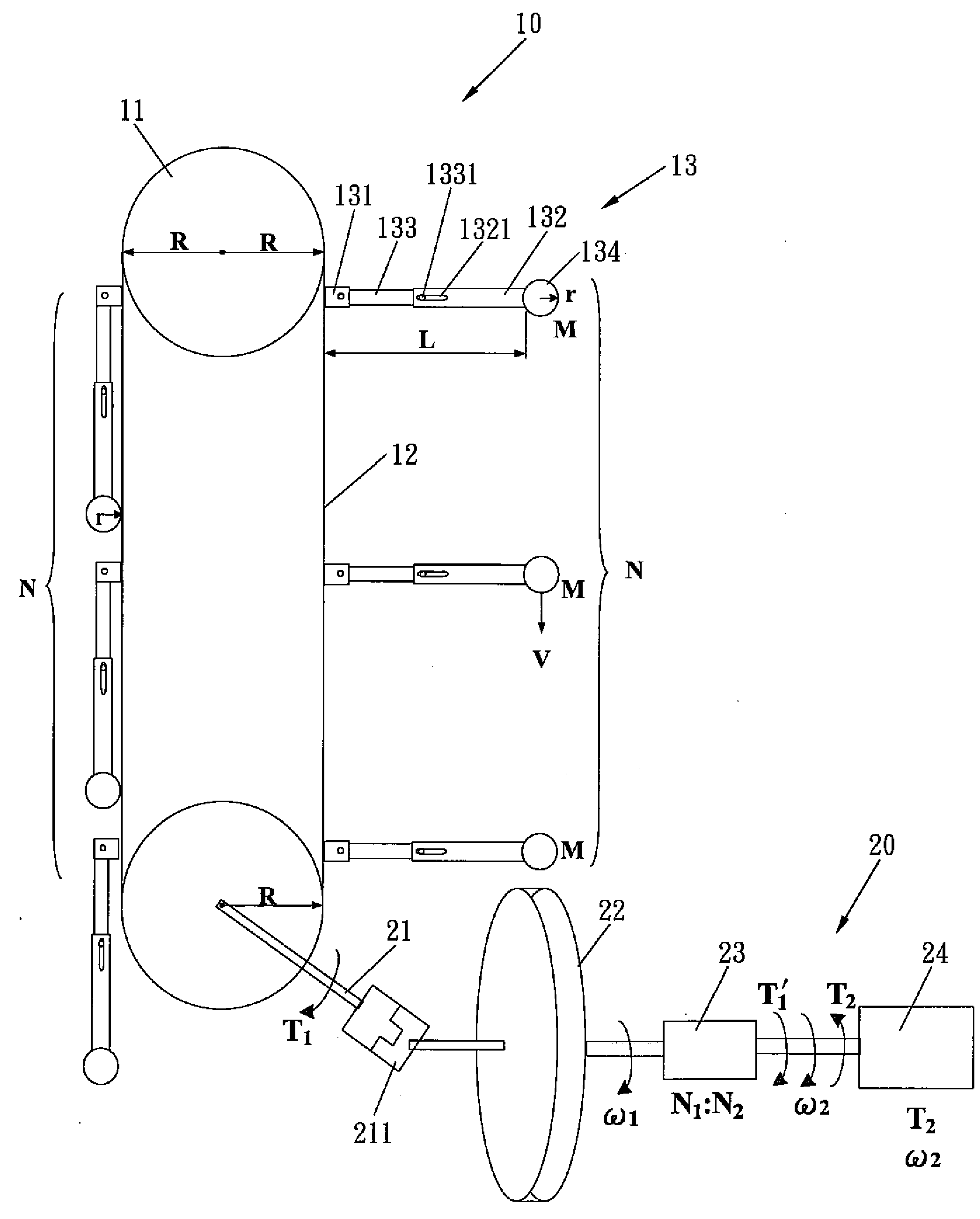
[0028]The gravity power generation mechanism in accordance with the present invention comprises a gravity energy conversion unit 10 and at least one power generating unit 20, and is characterized in that:

[0029]The gravity energy convention unit 10 includes two wheel members 11, a transmitting member 12 and a plurality of swing arms 13, which is pivotally coupled with at least two wheel members 11. The transmitting member 12 is mounted on the two wheel members 11, and the transmitting member 12 is drivingly connected with the two wheel members 11. These single directional swing arms 13 are equidistantly positioned outside the transmitting member 12 by the single directional pivot seats 131. The single directional pivot seats 131 only allow the respective swing arms 13 to pivotally rotate in opposite direction of the transmitting member 12 (such as the negative allowable free angle is vertical 90 degrees). The single swing arm 13 includes at least one swing rod 132 and a pivot rod 133...

second embodiment

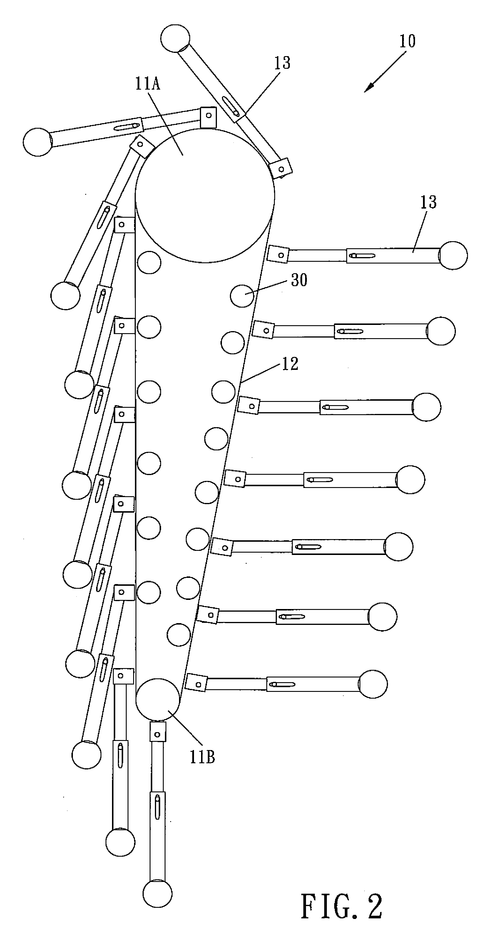
[0051]FIGS. 2-3 show a gravity power generation mechanism in accordance with the present invention in which the same structures will not be described except the improved design.

[0052]The gravity energy conversion unit 10 includes a larger wheel member 11A, a smaller wheel member 11B. Inside the transmitting member 12 which is used together with the larger wheel member 11A and the smaller wheel member 11B is installed an assistant wheel 30. The gravity energy conversion unit 10 is sequentially disposed with, from the top down, the larger wheel member 11A, the smaller wheel member 11B along the direction of gravity, so that the outwards-casting action of the single directional swing arms 13 will produce a much larger positive torque by using the larger diameter of the larger wheel member 11A, after the respective single directional swing arms 13 rise to the top end.

[0053]In addition, the power generating unit 20 includes a connecting shaft 21, a larger gear 31, a smaller gear 32 and a...


PUM


Abstract

A gravity power generation mechanism utilizes a gravity energy conversion unit to convert the gravity potential energy into the kinetic energy. The gravity energy conversion unit produces positive torques by adopting outward-spreading single directional swing arms and reduces the negative torques by cooperating with the folding action of the single directional swing arms, so as to perform a long-time, effective and continuous energy conversion of converting gravity potential energy into the kinetic energy. Next, the kinetic energy will be transmitted to a power generating unit to perform another energy conversion of converting the kinetic energy into the electric energy. And finally, a power supply system is used to transmit the electric energy out. By such arrangements, the gravity power generation mechanism not only has the advantages, such as: more simplified in structure, higher conversion ratio, and more environment-friendly but only needs a little of starting energy to perform a long-time energy conversion.

Description

BACKGROUND OF THE INVENTION[0001]1. Field of the Invention[0002]The present invention relates to a power generation mechanism, and more particularly to a gravity power generation mechanism which has the advantages such as: more simplified in structure, higher energy conversion ratio, and more environment-friendly and only needs a little of starting energy to perform a long-time energy output.[0003]2. Description of the Prior Art[0004]Recently, the energy source which can adequately produce energy is insufficient, and this has become an urgent problem to be solved for every country. The energy can be produced by various energy sources, such as thermal energy, light energy, wind energy. The problems of several common energy sources are respectively described as below.[0005]The most common energy source is the fossil fuel (such as crude oil, natural gas and coal). The fossil fuel generally produces high thermal energy or explosion energy through combustion for enabling the engine to us...

Claims


Application Information

Patent Timeline
IPC IPC(8): F03G3/08
CPCF03G3/06F03G7/10F03G3/08F03G7/107
Inventor WANG, CHUN-CHAOWANG, YUH-SUIANG
Owner WANG CHUN CHAO
Learn More