Photovoltaic power generation controller and power evaluation method in photovoltaic power generation control

a power generation controller and photovoltaic technology, applied in the direction of electric variable regulation, process and machine control, instruments, etc., can solve the problems of increasing product cost, no expected accuracy, and low resolution of adcs mounted in inexpensive mcs, so as to improve the accuracy of mppt and achieve high gain. , the effect of high accuracy

Inactive Publication Date: 2009-05-07
TOKYO DENKI UNIVERSITY
View PDF14 Cites 34 Cited by
  • Summary
  • Abstract
  • Description
  • Claims
  • Application Information

AI Technical Summary

Benefits of technology

[0036]According to the photovoltaic power generation control technique of the invention, MPPT control is started while giving a predetermined variation width to a modulation for an electric converter, and switching to power evaluation only with ripple components remaining after removing direct-current components is employed in the vicinity of MMP, whereby an amplifier with an extremely high gain can be used for MPPT control, leading to high-accuracy MPPT covering a wide range of solar radiation amounts. Further, as a result of the above, when performing MPPT using MCs, a minute power change can

Problems solved by technology

Many ADCs mounted in inexpensive MCs each have a low resolution and much internal noise, and have no expected accuracy.
Therefore, a high-solution ADC is required to decrease variation width to raise the MPPT accuracy of after MPP convergence in the hill-climbing method, but this leads to an increase in product cost.
Meanwhile, in many MPPT control circuits not only employing a hill-climbing method but also other methods, MPPT accuracy deteriorating during periods of low solar radiation is kno

Method used


Image

  • Photovoltaic power generation controller and power evaluation method in photovoltaic power generation control
  • Photovoltaic power generation controller and power evaluation method in photovoltaic power generation control
  • Photovoltaic power generation controller and power evaluation method in photovoltaic power generation control

Examples


first embodiment

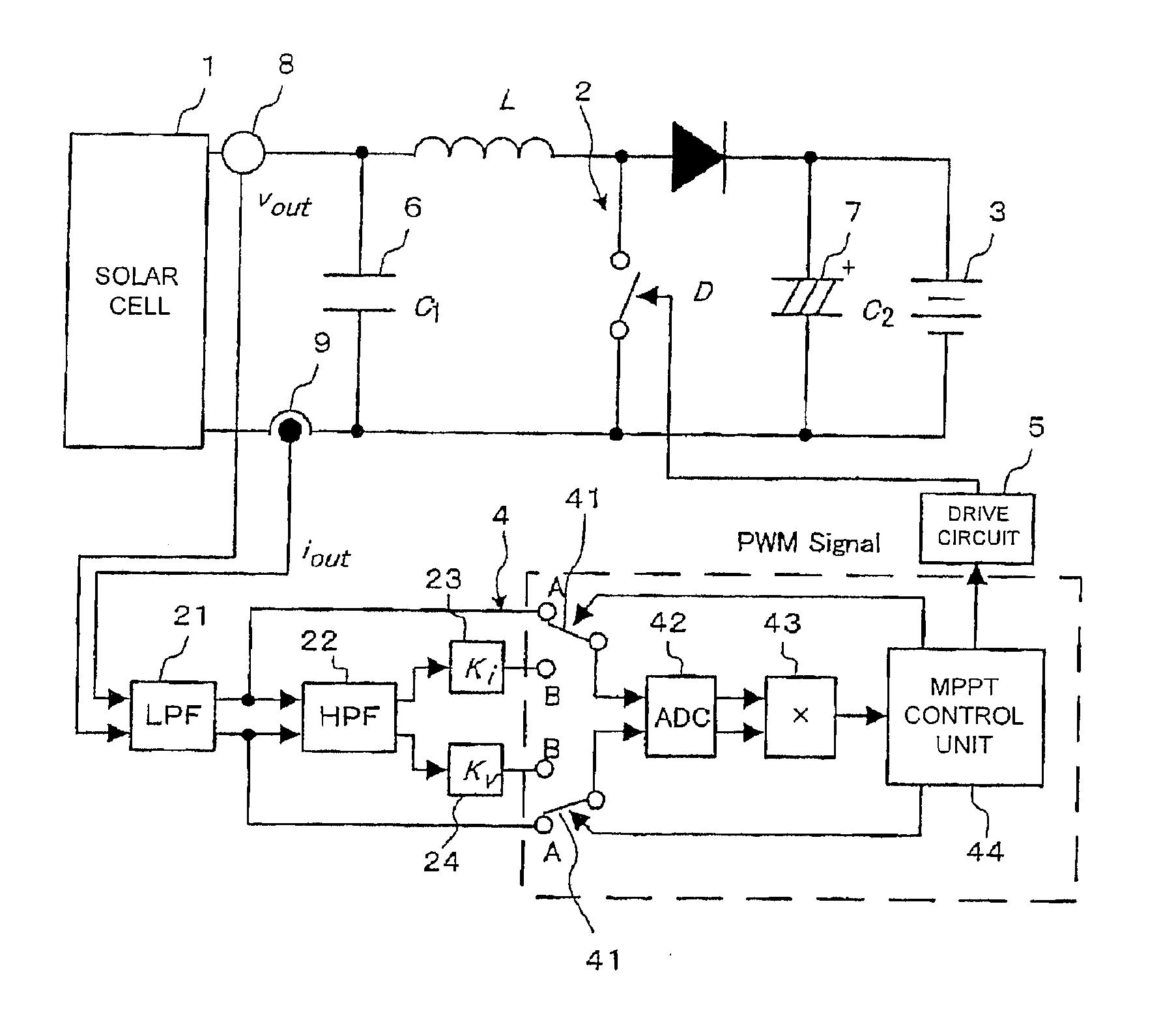
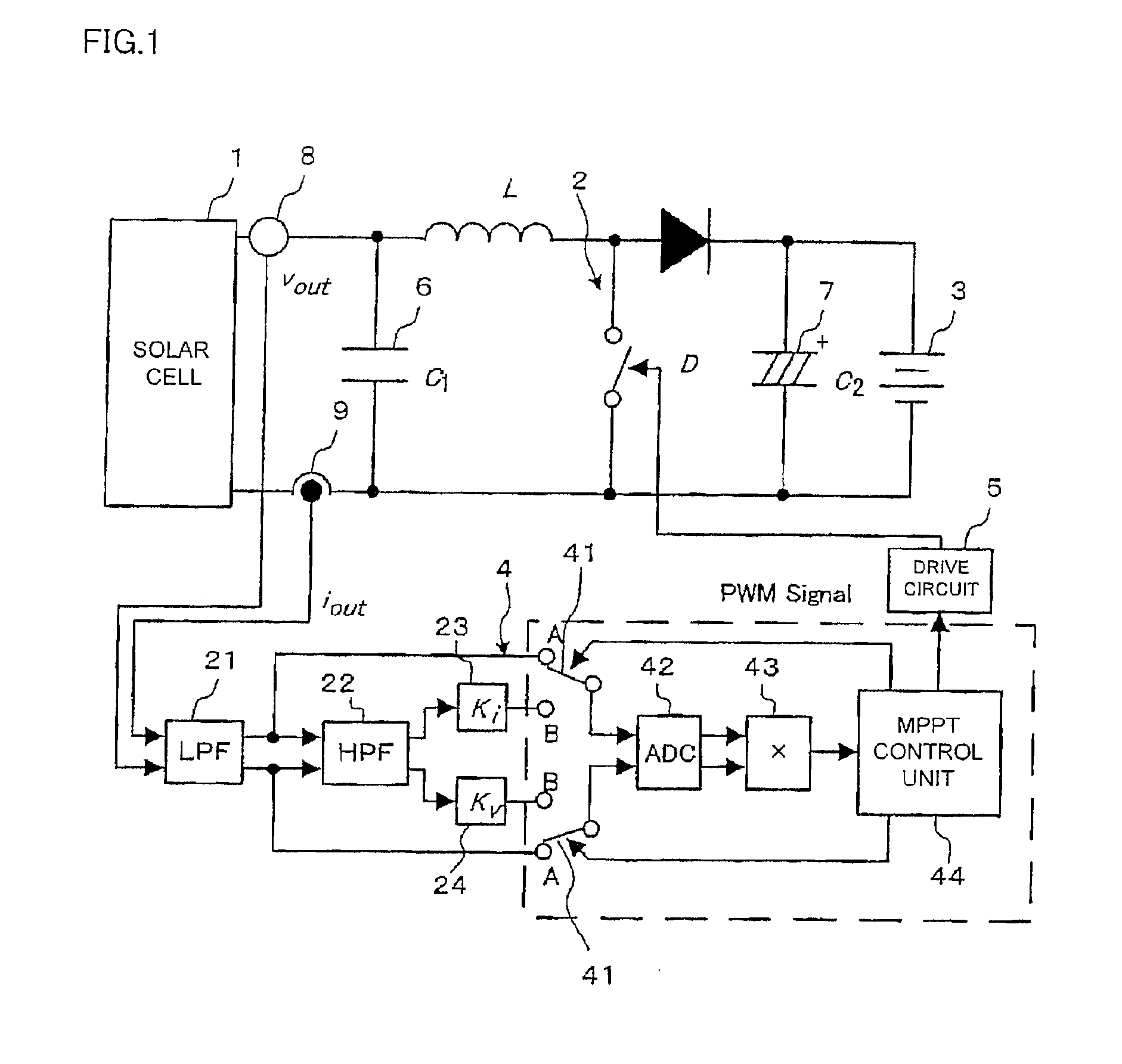
[0047]FIG. 1 shows a system configuration of a photovoltaic power generation controller according to a first embodiment of the invention. The photovoltaic power generation controller in this embodiment is composed of a solar cell 1, a step-up chopper circuit 2, a battery 3 serving as a secondary battery as a load, a control circuit 4, and a gate drive circuit 5. A smoothing capacitor 6 is provided between the solar cell 1 and the chopper circuit 2, and a smoothing capacitor 7 is provided between the chopper circuit 2 and the battery 3 that serves as a load. Also, a voltage detector 8 for detecting an output voltage of the solar cell 1 and a current detector 9 for detecting an output current of the solar cell 1 are provided. A detected voltage signal of the voltage detector 8 and a detected current signal of the current detector 9 are input to the control circuit 4 via a low-pass filter (LPF) 21.

[0048]The control circuit 4 is provided with a high-pass filter (HPF) 22, a current ampli...

second embodiment

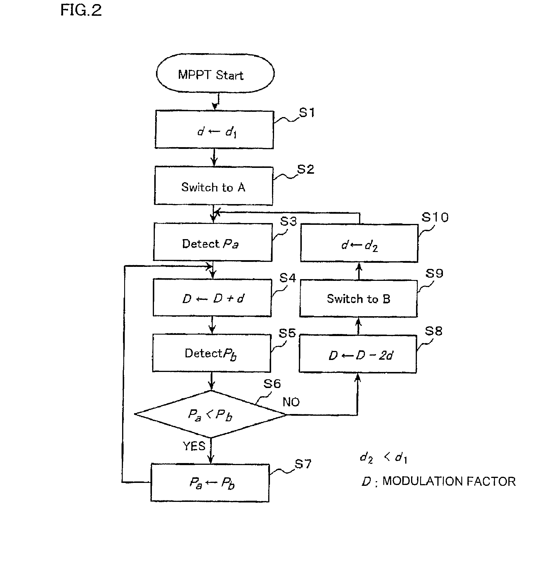
[0057]A second embodiment of the invention will be described with reference to FIG. 3. A characteristic of this embodiment resides in that: the MPPT control unit 44 determines the presence of saturation of the amplifiers 23 and 24; and a hill-climbing method is executed again from the beginning in the case of occurrence of saturation, meanwhile, MPPT control is continued with an improved hill-climbing method as in the first embodiment in the case of non-occurrence of saturation. Accordingly, the system configuration of this embodiment is the same as in the first embodiment, but MPPT control is performed according to the flowchart of FIG. 3.

[0058]In this embodiment, the MPPT control unit 44 starts operation from open circuit voltage Pa after setting the switches 41 to sides A, and searches for MPP with large variation width d1 (steps S1-S7). Then, the MPPT control unit 44 determines the presence of occurrence of saturation of the amplifiers 23 and 24 based on whether or not the ADC 4...

third embodiment

[0066]A third embodiment of the invention will be described. When assuming that di / de, i.e., a is known at an arbitrary operating point of a voltage-current characteristic of the solar cell 1, MPPT control can be performed also with the power value obtained from the product of the values obtained by, as shown in expression 2, subtracting E and I, which satisfy the relationship in expression 5, respectively from the measurement values of a voltage and a current.

[0067]The case where power is calculated by removing direct-current components when the operating point is represented by (Ep, Ip) is considered. Removing the direct-current components with a high-pass filter corresponds to employing the following expressions in expression 2,

E=Ep   [Expression 10]

I=Ip   [Expression 11]

[0068]Meanwhile, when removing Ep from a voltage value, value I that can be subtracted from a current value is expressed by the following expression based on expression 5.

I=−αEp   [Expression 12]

[0069]When (Ep, I...


PUM


Abstract

A photovoltaic power generation controller, in which minute power change is detected even with a low-resolution AD converter, thereby being capable of performing maximum power point tracking control with high accuracy, is provided. In the photovoltaic power generation controller of the invention, a control circuit 44 shifts switches 41 to respective output A sides of a voltage detector 8 and a current detector 9; gives a low-frequency ripple component to an operating voltage of a solar cell 1 while increasing modulation factor D by predetermined variation width d, to start maximum power point search from an open circuit voltage side; confirms a maximum power point passage when: an operating point oscillates in the vicinity of the maximum power point; and a power value, which is output by a power detector 43, after update of the modulation factor becomes smaller than a power value before update of the modulation factor; and switches the switches 41 to respective output sides of amplifiers 23 and 24 to continue the maximum power point tracking control.

Description

CROSS-REFERENCES TO RELATED APPLICATIONS[0001]The entire disclosure of Japanese Patent Application No. 2007-289858, filed on Nov. 7, 2007, is expressly incorporated herein by reference.BACKGROUND[0002]1. Technical field[0003]The present invention relates to a photovoltaic power generation controller and a power evaluation method in photovoltaic power generation control.[0004]2. Related Art[0005]In order to take power efficiently from a solar cell, the solar cell always needs to be made to operate at the maximum power point (MPP). Therefore, a general photovoltaic power generation system is provided with a maximum power point tracking control circuit (MPPT).[0006]Many types of MPPT methods have already been reported, and one of those is a control method referred to as a hill-climbing method. In this control method, an oscillation component (hereinafter referred to as a “ripple component”) with a constant variation width is given to an operating voltage of a solar cell at a low freque...

Claims


Application Information

Patent Timeline
IPC IPC(8): G05F5/02
CPCG05F1/67Y10S323/906Y02E10/58H02M3/157Y02E10/56
Inventor YOSHIDA, TOSHIYAOHNIWA, KATSUMIOHTSUBO, MICHIO
Owner TOKYO DENKI UNIVERSITY
Why Eureka
Try Eureka