Optical unit, method for controlling drive, and holographic apparatus

a technology of optical units and drives, applied in the direction of data recording, instruments, recording/reproducing/erasing using optical interference patterns, etc., can solve the problems of slow response time, deterioration of hologram recording and reconstruction performance, etc., to achieve high-speed response, reduce the number of components that are necessary for realizing image stabilization functions, and maintain the voltage level

Inactive Publication Date: 2009-05-07
SONY CORP
View PDF2 Cites 15 Cited by
  • Summary
  • Abstract
  • Description
  • Claims
  • Application Information

AI Technical Summary

Benefits of technology

[0052]As described above, according to the embodiments of the present invention, a shutter function is realized by controlling the frequency of a voltage applied to an acousto-optic medium having a photoelastic characteristic. That is, the necessity of an AOM that provides a shutter function by changing the amplitude of the applied voltage can be removed, and therefore, the level of the applied voltage can be maintained constant.
[0053]As a result, according to the embodiments of the present invention, a shutter function can be provided without causing a thermal change in an acousto-optic medium, and therefore, an optical axis shift that may occur when an AOM is used can be prevented.
[0054]In addition, since the shutter function is realized by using a photoelastic effect of an acousto-optic medium, a shutter having a significantly high-speed response can be achieved, as compared with a mechanical shutter.
[0055]In particular, in the holographic apparatus including the optical unit according to the above-described embodiment, when, in order to realize an image stabilization function, an emitted beam is scanned at predetermined interva...

Problems solved by technology

However, the AOM 51 serving as a shutter has the following problems.
The deviation of the laser beam causes the hologram record...

Method used


Image

  • Optical unit, method for controlling drive, and holographic apparatus
  • Optical unit, method for controlling drive, and holographic apparatus
  • Optical unit, method for controlling drive, and holographic apparatus

Examples


Embodiment Construction

[0066]Various exemplary embodiments of the present invention are described below with reference to the accompanying drawings.

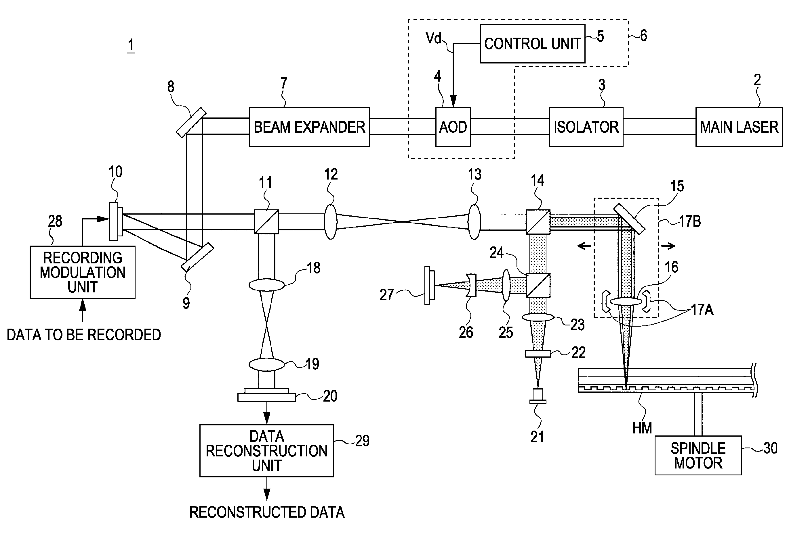
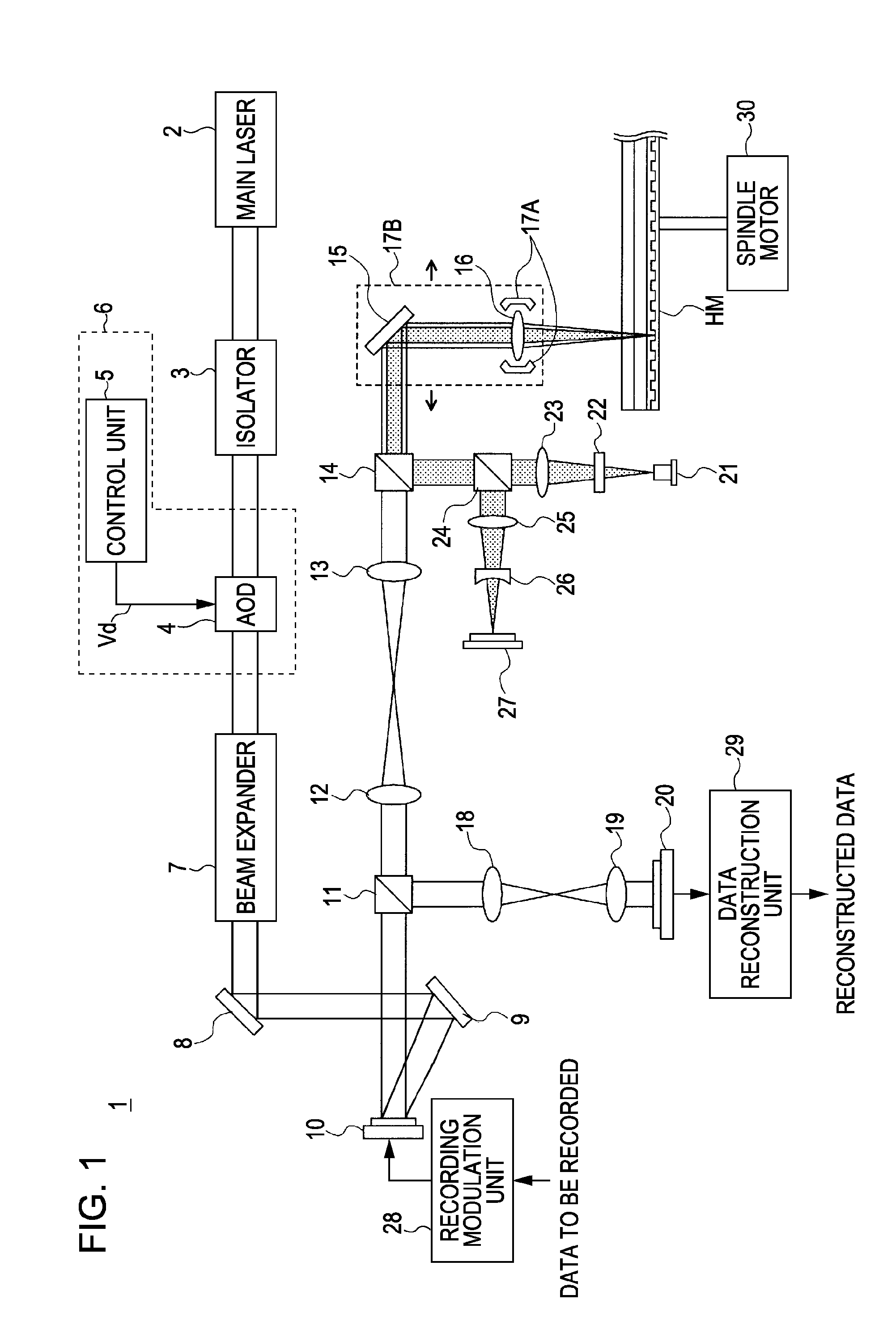
[0067]FIG. 1 is a block diagram illustrating an exemplary internal configuration of a hologram recording and reconstructing apparatus 1, which is a holographic apparatus according to the present embodiment. Note that FIG. 1 illustrates only components of an optical system of the hologram recording and reconstructing apparatus 1. The other components are not shown in FIG. 1.

[0068]According to the present embodiment, a hologram recording and reconstructing method called a “coaxial method” is employed. That is, a signal light beam and a reference light beam are disposed on the same axis. These two light beams are emitted onto a holographic recording medium HM so that data is recorded using interference fringes. When data is reconstructed, the reference light beam is emitted onto the holographic recording medium HM so that the data recorded using the interference ...


PUM


Abstract

An optical unit includes an acousto-optic deflector and a drive control unit. The drive control unit controls the acousto-optic deflector by changing a frequency of a voltage applied to an acousto-optic medium of the acousto-optic deflector to a frequency in a first frequency range during a first period representing a deflection control period and changing the frequency of the voltage to a frequency in a second frequency range different from the first frequency range during a second period representing a transmittance control period.

Description

CROSS REFERENCES TO RELATED APPLICATIONS[0001]The present invention contains subject matter related to Japanese Patent Application JP 2007-289692 filed in the Japanese Patent Office on Nov. 7, 2007, the entire contents of which are incorporated herein by reference.BACKGROUND OF THE INVENTION[0002]1. Field of the Invention[0003]The present invention relates to an optical unit using an acousto-optic deflector (AOD), a method for controlling the AOD, and a holographic apparatus that record and reconstruct data on a holographic recording medium using interference fringes generated by a signal light beam and a reference light beam.[0004]2. Description of the Related Art[0005]Recently, a holographic recording and reconstructing method for recording data using interference fringes generated by a signal light beam and a reference light beam has been developed.[0006]FIG. 8 illustrates a typical internal configuration of an existing holographic recording and reconstructing apparatus 50. In pa...

Claims


Application Information

Patent Timeline
IPC IPC(8): G03H1/30G02F1/33
CPCG02F1/0131G02F1/113G02F1/33G11B7/128G03H2001/0216G11B7/0065G11B7/083G02F2203/12
Inventor OKADA, HITOSHISEKO, SATORU
Owner SONY CORP
Why Eureka
Try Eureka