Control device of direct injection internal combustion engine

a technology of control device and internal combustion engine, which is applied in the direction of electric control, ignition automatic control, instruments, etc., can solve the problems of increasing hc emission quantity, torque reduction, etc., and achieve the effect of increasing rotation speed

Inactive Publication Date: 2009-05-07
DENSO CORP
View PDF1 Cites 32 Cited by
  • Summary
  • Abstract
  • Description
  • Claims
  • Application Information

AI Technical Summary

Benefits of technology

[0008]It is an object of the present invention to provide a control device of a direct injection internal combustion engine capable of stabilizing a combustion state even when a crank angle at injection end timing deviates toward a delayed crank angle side due to increase in rotation speed of the internal combustion engine.

Problems solved by technology

As a result, the combustion state worsens, causing a misfire and decrease in torque or increase in a HC emission quantity due to incomplete combustion.
Such the problems can arise similarly in the technology described in Patent document 1 (that sets the injection start timing such that the injection ends at timing advanced from the ignition timing by a predetermined crank angle).

Method used


Image

  • Control device of direct injection internal combustion engine
  • Control device of direct injection internal combustion engine
  • Control device of direct injection internal combustion engine

Examples


first embodiment

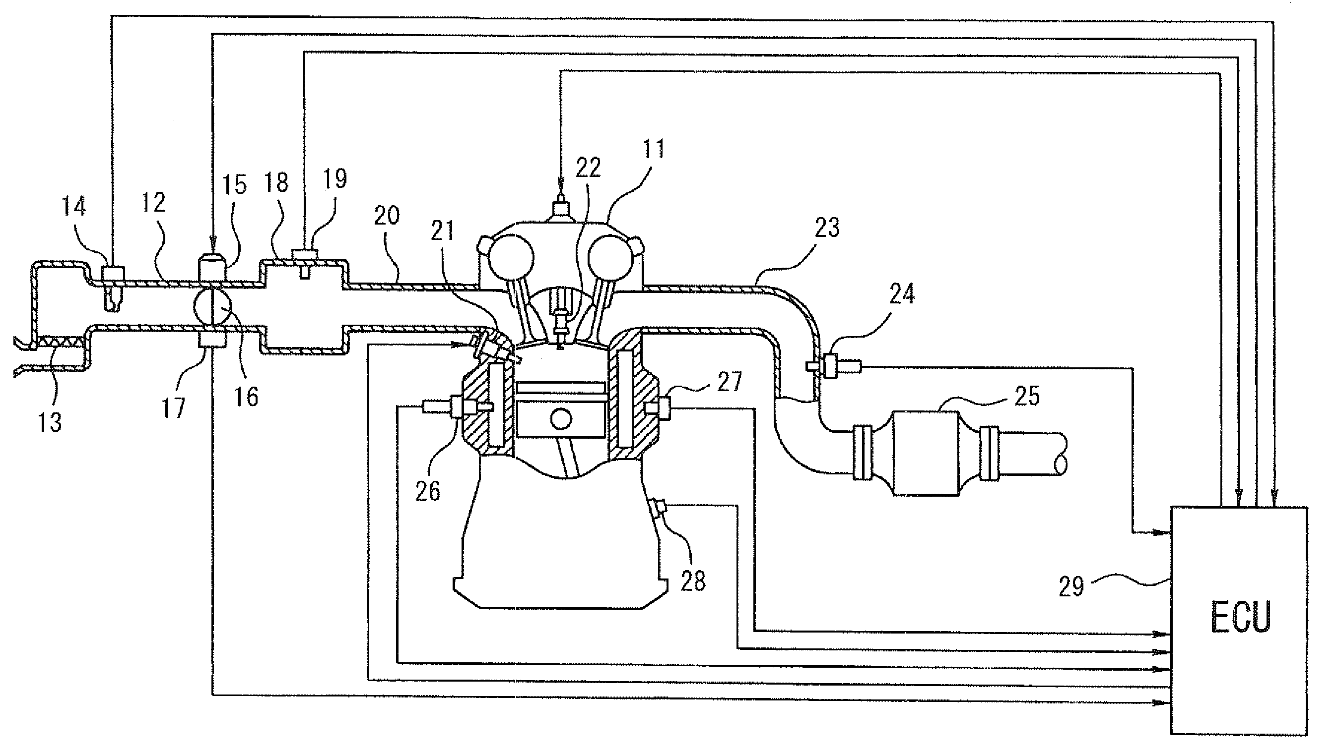
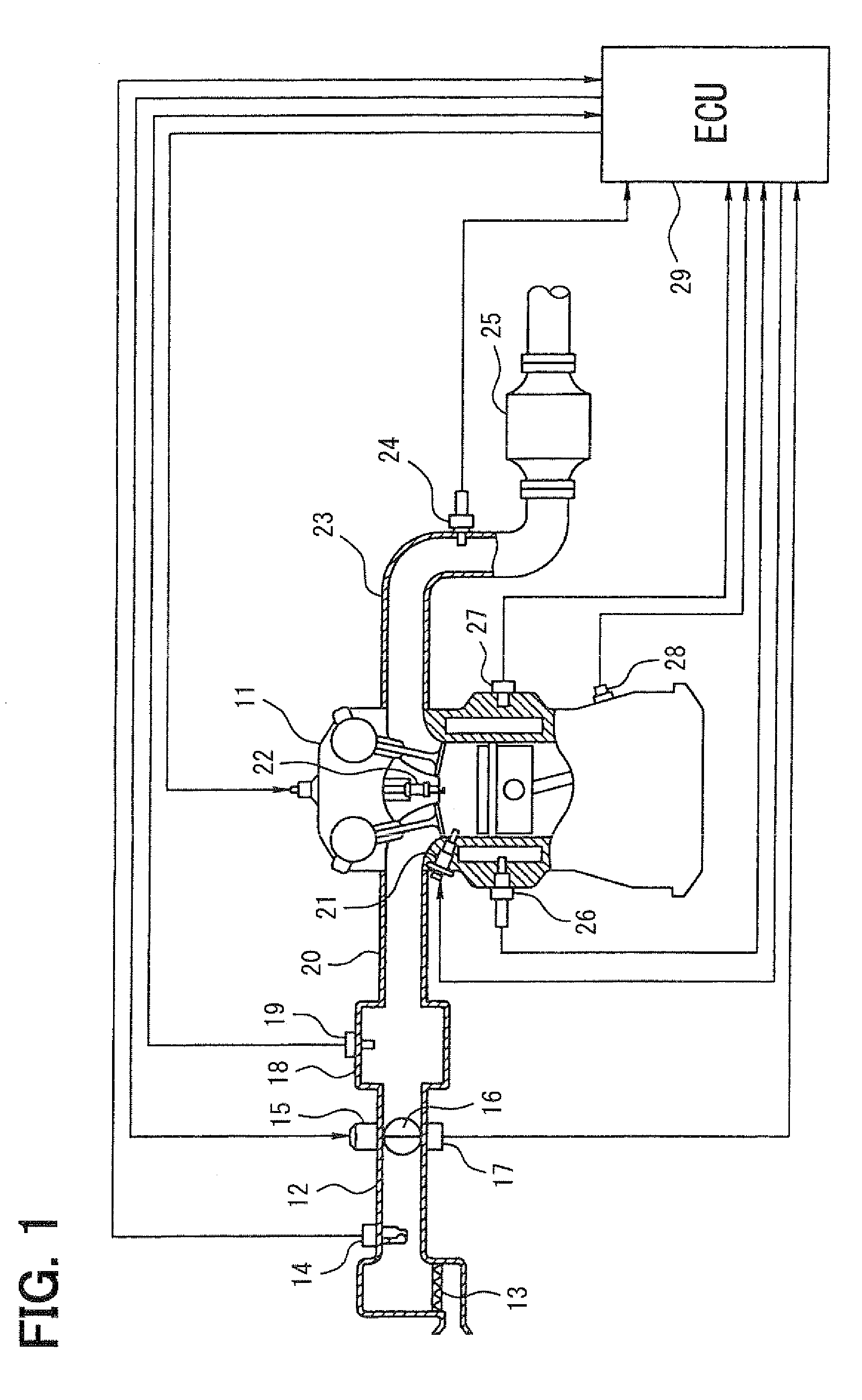
[0032]the present invention will be described with reference to FIGS. 1 to 5. First, a general configuration of an entire engine control system will be explained with reference to FIG. 1. An air cleaner 13 is provided in the most upstream portion of an intake pipe 12 of a direct injection engine 11 as a direct injection internal combustion engine. An airflow meter 14 for sensing an air intake quantity is provided downstream of the air cleaner 13. A throttle valve 16, whose opening degree is regulated by a motor 15, and a throttle position sensor 17 for sensing an opening degree of the throttle valve 16 (a throttle opening degree) are provided downstream of the airflow meter 14.

[0033]A surge tank 18 is provided downstream of the throttle valve 16, and an intake pipe pressure sensor 19 for sensing intake pipe pressure is provided in the surge tank 18. An intake manifold 20 for introducing the air into respective cylinders of the engine 11 is provided to the surge tank 18. Injectors 21...

second embodiment

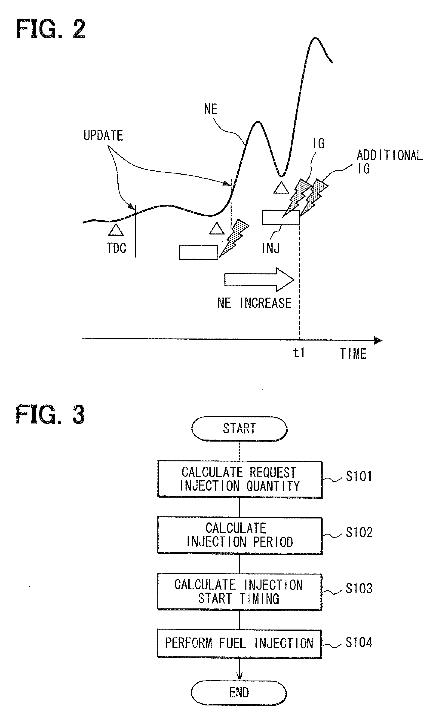
[0049]Therefore, in the second embodiment, an additional ignition control routine shown in FIG. 7 (described in detail later) is executed. Thus, the additional ignition of the spark plug 22 is performed at timing t2 when a predetermined time a (for example, a time necessary for the injected fuel to be atomized) elapses after the actual injection end timing t1 of the injector 21.

[0050]Hereafter, processing contents of the additional ignition control routine of FIG. 7 will be explained. In the routine, it is determined whether the engine rotation speed NE is increasing in S401. When it is determined that the engine rotation speed NE is increasing, the process proceeds to S402. In S402, it is determined whether a predetermined time a has elapsed after the actual injection end timing t1 of the injector 21 of the present injection cylinder (for example, timing when the injector 21 is closed or the timing when the injection period has elapsed after the injection start timing of the inject...

third embodiment

[0055]In the third embodiment, an additional ignition control routine shown in FIG. 8 (described in detail later) is performed. Thus, an engine rotation speed increasing degree (for example, an increase amount of the engine rotation speed NE) due to the present combustion is sensed and the crank angle at the injection end timing of the injector 21 of the present injection cylinder is predicted based on the sensed engine rotation speed increasing degree. Then, the additional ignition is performed at the timing substantially the same as the predicted injection end timing.

[0056]Next, processing contents of the additional ignition control routine shown in FIG. 8 will be explained. In the routine, it is determined in S501 whether the engine rotation speed NE is increasing. When it is determined that the engine rotation speed NE is increasing, the process proceeds to S502, in which the engine rotation speed increasing degree due to the present combustion is calculated. In this case, for e...


PUM


Abstract

When engine rotation speed is increasing in a compression stroke injection mode, a control device determines that a crank angle at injection end timing of an injector deviates toward a delayed crank angle side and performs additional ignition at timing when (or immediately before or after) a crank angle at actual injection end timing of the injector of a present injection cylinder is reached. Thus, even when the crank angle at the injection end timing deviates toward the delayed crank angle side with respect to preset original ignition timing, a combustion state can be stabilized by performing the additional ignition at timing, at which a suitable stratified mixture gas is formed in a cylinder, through the execution of the additional ignition at the timing substantially the same as the actual injection end timing.

Description

CROSS REFERENCE TO RELATED APPLICATION[0001]This application is based on and incorporates herein by reference Japanese Patent Application No. 2007-290224 filed on Nov. 7, 2007.BACKGROUND OF THE INVENTION[0002]1. Field of the Invention[0003]The present invention relates to a control device of a direct injection internal combustion engine that sets injection start timing of an injector, which injects fuel into a cylinder of the internal combustion engine, and ignition timing of a spark plug such that injection end timing of the injector and the ignition timing of the spark plug have a predetermined relationship.[0004]2. Description of Related Art[0005]In recent years, as one of internal combustion engines mounted in vehicles, there has been a direct injection internal combustion engine having features of low fuel consumption, low exhaust emission, and high output at the same time. In the case of a certain direct injection internal combustion engine (for example, refer to Patent docume...

Claims


Application Information

Patent Timeline
Patent Type & Authority Applications(United States)
IPC IPC(8): F02D45/00
CPCF02P5/06F02D37/02
Inventor KITA, MASAYUKI
Owner DENSO CORP
Why Eureka
Try Eureka