Detection of faults in an injector arrangement

a fuel injector and fault technology, applied in the direction of machines/engines, electrical control, instruments, etc., can solve the problems of short circuit faults, catastrophic engine failure, and failure of drive circuits, so as to prevent damage to piezoelectric stacks, minimise the required processor and sampling resources, and reduce the time cost

Inactive Publication Date: 2009-05-14
DELPHI INT OPERATIONS LUXEMBOURG S A R L
View PDF8 Cites 33 Cited by
  • Summary
  • Abstract
  • Description
  • Claims
  • Application Information

AI Technical Summary

Benefits of technology

[0036]A second voltage control regime is performed at engine start-up, when the actuators are initially charged from a low voltage to a suitably high target voltage in preparation for being discharged to perform injection events. A third voltage control regime is performed when the engine is turned off, to actively discharge the actuators form a high voltage to a suitably low target voltage to prevent damage to the piezoelectric stacks.
[0037]Advantageously, when the invention is performed during a voltage control regime, the voltage samples performed under to the voltage control regime are also used in the fault detection method. As such, the present invention can be incorporated into a voltage control regime with very little time cost because no additional analogue-to-digital converter (ADC) reads are required over and above those required in the voltage control regime. Furthermore, as the voltage samples are used both in the voltage control regime and in the diagnostic scheme, this minimises the required processor and sampling resources. This serves to reduce costs which would otherwise be required to upgrade the micro...

Problems solved by technology

Like any circuit, faults may occur in a drive circuit.
In safety critical systems, such as diesel engine fuel injection systems, a fault in the drive circuit may lead to a failure of the injection...

Method used


Image

  • Detection of faults in an injector arrangement
  • Detection of faults in an injector arrangement
  • Detection of faults in an injector arrangement

Examples


Embodiment Construction

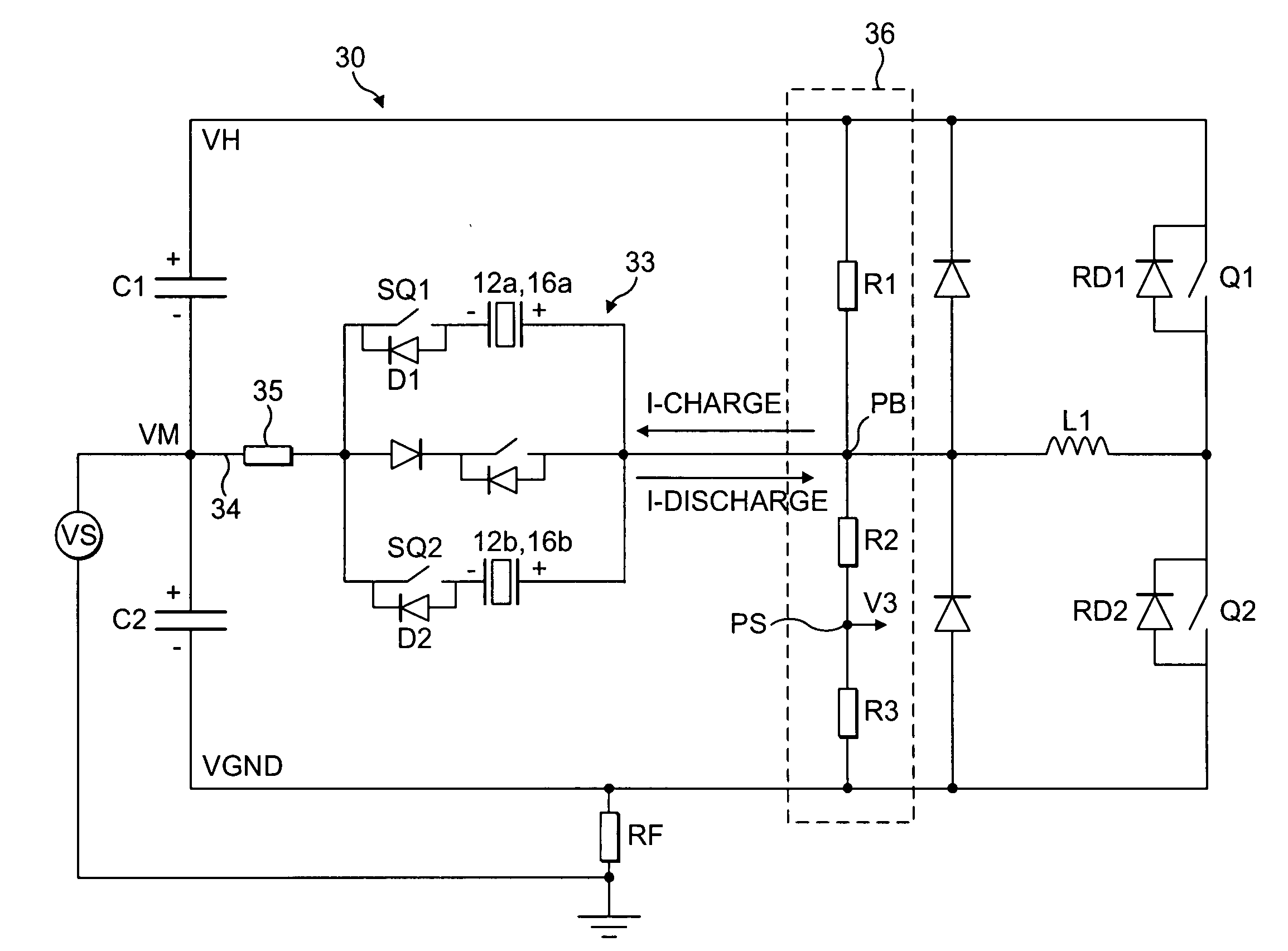
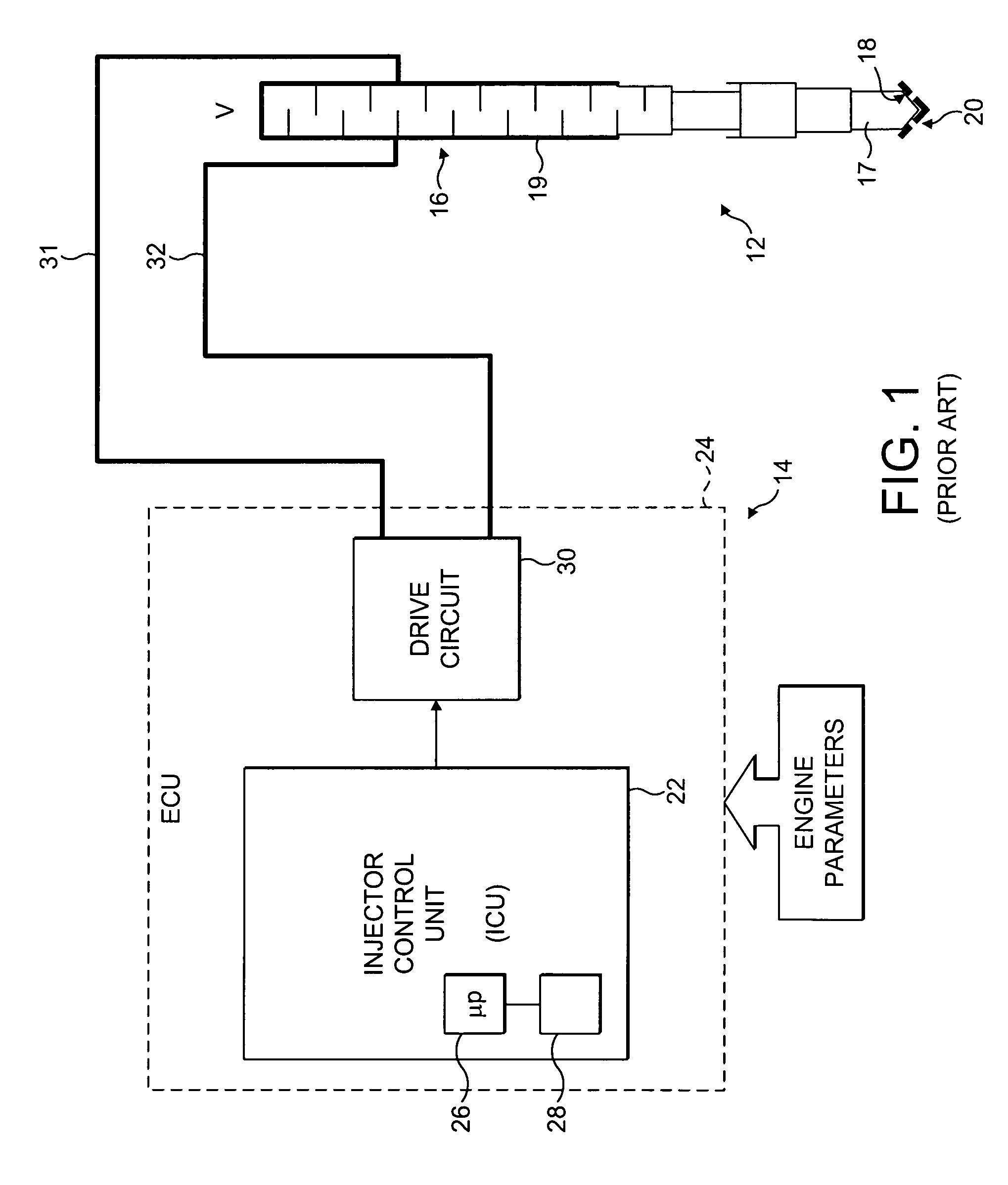
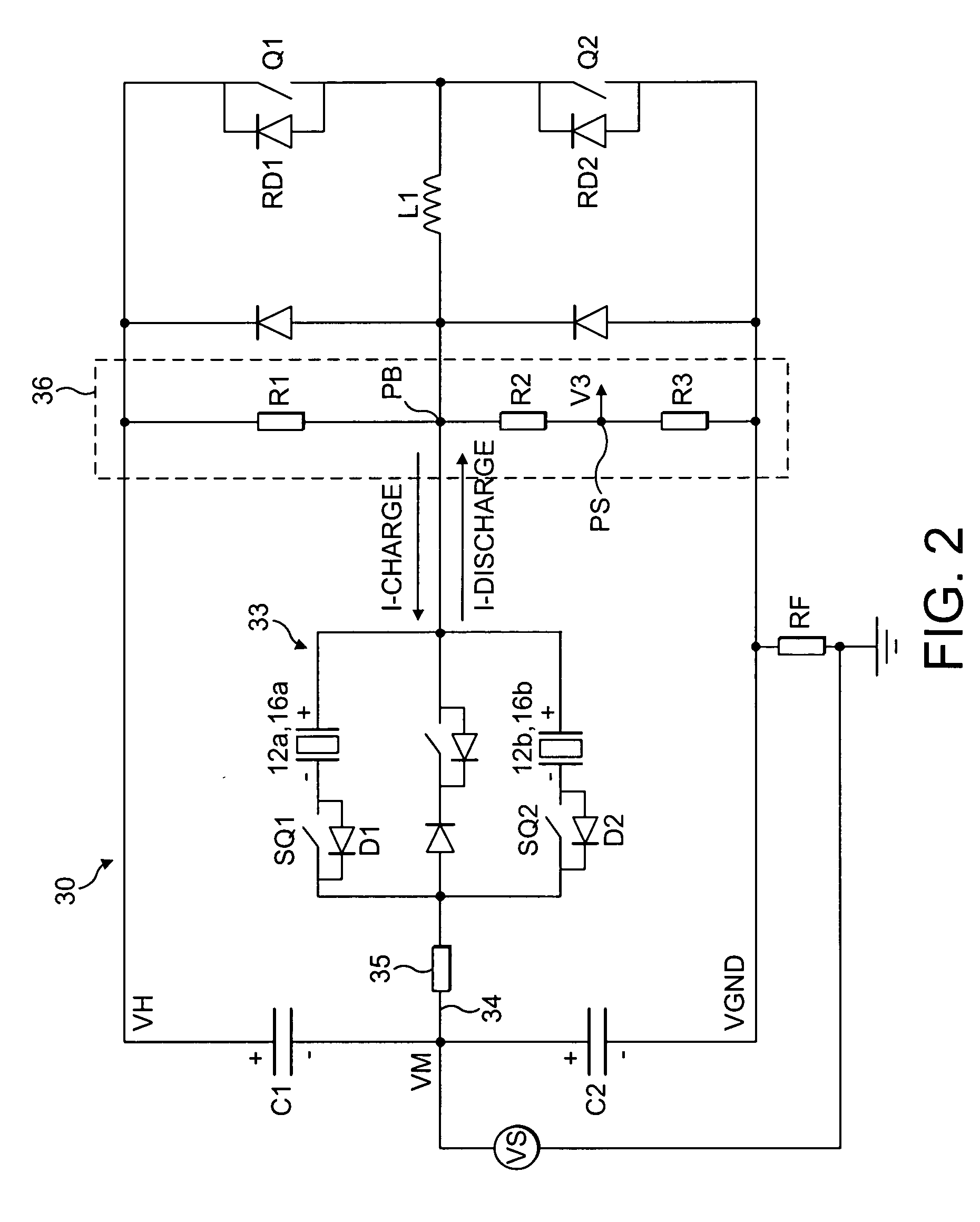
[0052]Reference has already been made to FIG. 1, which shows a typical piezoelectric fuel injector 12 connected to an injector drive circuit 30 of an ECU 24. Referring now to FIG. 2, this is a circuit diagram of an injector drive circuit 30 similar to the drive circuit in FIG. 1. In FIG. 2, the injector drive circuit 30 is connected to an injector bank 33 comprising a pair of discharge-to-inject piezoelectric injectors 12a, 12b.

[0053]The drive circuit 30 includes high, mid and ground voltage rails VH, VM and VGND respectively. The drive circuit 30 is generally configured as a half H-bridge with the mid voltage rail VM serving as a bi-directional middle current path 34. The piezoelectric injectors 12a, 12b comprise piezoelectric actuators 16a, 16b (hereinafter referred to simply as ‘actuators’), which are connected in parallel in the middle circuit branch 34 of the injector drive circuit 30. The actuators 16a, 16b are located between, and coupled in series with, an inductor L1 and a...


PUM


Abstract

A fault detection method is provided for detecting faults in an injector arrangement. The injector arrangement comprises one or more piezoelectric fuel injectors connected in an injector drive circuit, and the injector drive circuit is arranged to control operation of the one or more piezoelectric fuel injectors. The fault detection method includes determining a sample voltage at a sample point in the injector drive circuit at a first sample time. The sample voltage is the voltage on an injector or is related to the voltage on an injector. The method further includes calculating a range of predicted voltages expected at the sample point at a second sample time following the first sample time, and determining the sample voltage at the sample point at the second sample time. The presence of a fault is detected if the sample voltage determined at the sample point at the second sample time is not within the range of predicted voltages.

Description

TECHNICAL FIELD[0001]The present invention relates to a method for detecting faults in a fuel injector arrangement, and particularly to a method for detecting short circuit and open circuit faults in piezoelectric fuel injectors.BACKGROUND TO THE INVENTION[0002]In a direct injection internal combustion engine, a fuel injector is provided to deliver a charge of fuel to a combustion chamber prior to ignition. Typically, the fuel injector is mounted in a cylinder head with respect to the combustion chamber such that its tip protrudes slightly into the chamber in order to deliver a charge of fuel into the chamber.[0003]One type of fuel injector that is particularly suited for use in a direct injection engine is a so-called piezoelectric injector. A piezoelectric injector 12 and its associated control system 14 are shown schematically in FIG. 1.[0004]The piezoelectric injector 12 includes a piezoelectric actuator 16 that is operable to control the position of an injector valve needle 17 ...

Claims


Application Information

Patent Timeline
IPC IPC(8): G01R31/08
CPCF02D41/062F02D41/2096F02D41/221F02D2041/2003F02D2041/2006F02D2041/2051H02N2/06F02D2041/2072F02D2041/2082F02D2041/2089F02D2041/2093F02D2200/0602F02M51/0603F02D2041/2058
Inventor PERRYMAN, LOUISA J.HOPLEY, DANIEL JEREMY
Owner DELPHI INT OPERATIONS LUXEMBOURG S A R L
Why Eureka
Try Eureka