Illumination optical apparatus and projection exposure apparatus

an optical apparatus and projection technology, applied in the field of illumination technology and exposure technology, can solve the problems of large loss in quantity of illumination light, and low illumination efficiency, and achieve the effect of small loss in quantity of ligh

Inactive Publication Date: 2009-05-14
GEARBOX
View PDF103 Cites 72 Cited by
  • Summary
  • Abstract
  • Description
  • Claims
  • Application Information

AI Technical Summary

Benefits of technology

[0023]According to the present embodiments, for example, thicknesses of the birefringent members are set in their respective predetermined distributions, whereby the polarization after passage of the illumination light emitted from the light source, through the plurality of birefringent members, can be, for example, in a state consisting primarily of polarization in the circumferential direction around the optical axis in an annular region centered around the optical axis. An exit surface of the birefringent members is located, for example, at a position near the pupil plane of the illumination optical system, whereby the first object is illuminated with the illumination light (specific illumination beam) having passed through the annular region and kept in the predetermined polarization state consisting primarily of S-polarization, with little loss in quantity of light.

Problems solved by technology

In effecting the annular illumination by the conventional technology as described above, there was the problem of large loss in quantity of the illumination light to lower illumination efficiency if the polarization state of the illumination light was made to be linear polarization substantially matched with the circumferential direction of the annular region on the pupil plane of the illumination optical system.
This method used only energy in the predetermined linear polarization component out of the energy of the illumination light of random polarization, i.e., only approximately half energy as the illumination light onto the reticle, and thus posed the problem of large loss in quantity of the illumination light and large loss in exposure power on the wafer in turn, resulting in reduction in processing performance (throughput) of the exposure apparatus.
Similarly, in application of multipole illumination such as the dipole illumination or quadrupole illumination, there was also the problem of reduction in illumination efficiency if the polarization of the illumination light in each dipole or quadrupole region was attempted to be set in a predetermined state on the pupil plane of the illumination optical system.

Method used


Image

  • Illumination optical apparatus and projection exposure apparatus
  • Illumination optical apparatus and projection exposure apparatus
  • Illumination optical apparatus and projection exposure apparatus

Examples


Embodiment Construction

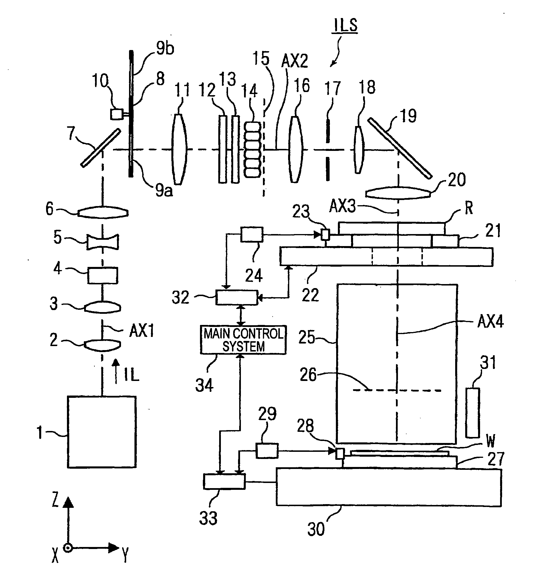
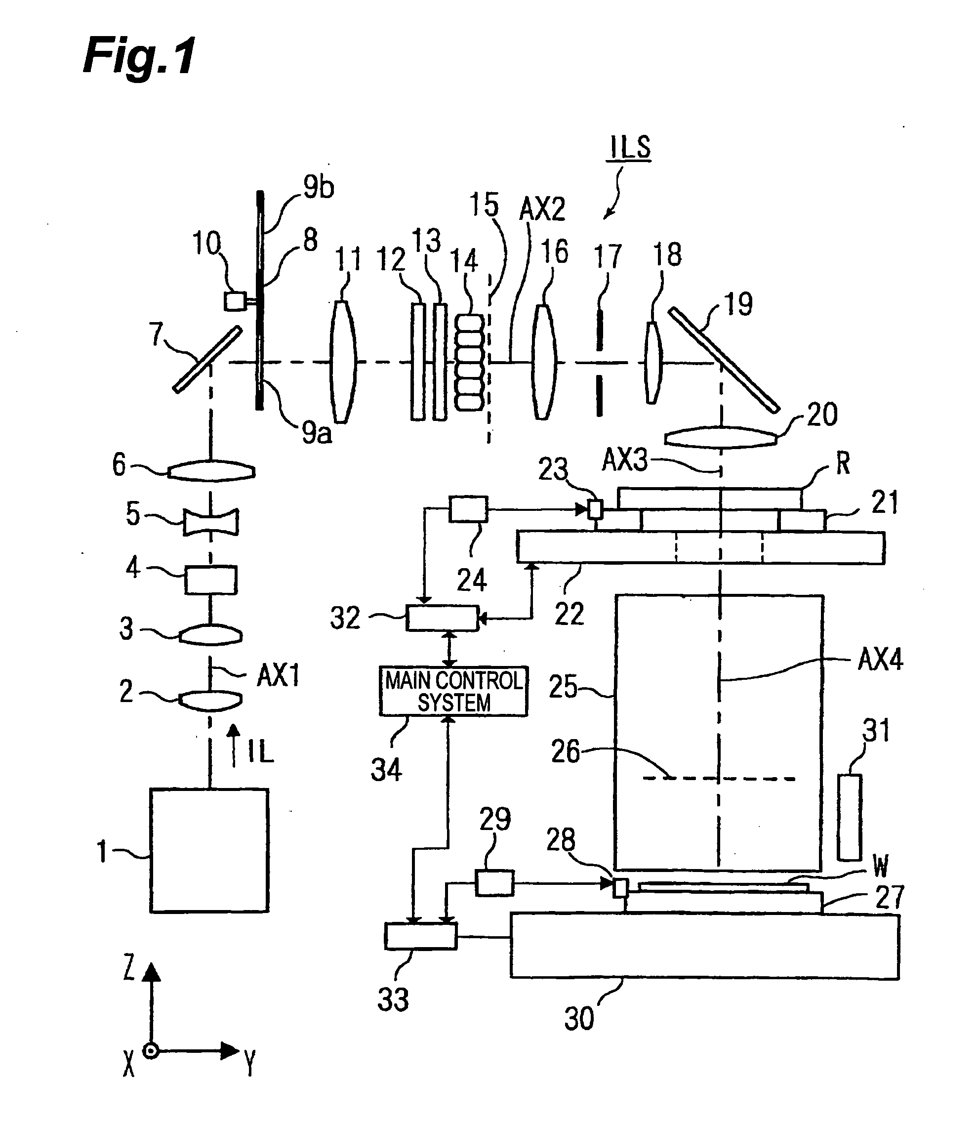
[0049]An example of preferred embodiment of the present invention will be described below with reference to the drawings. The present example is an application of the present invention to a case where exposure is performed by a projection exposure apparatus of the scanning exposure type (scanning stepper) according to the step-and-scan method.

[0050]FIG. 1 is a drawing showing a schematic configuration of the projection exposure apparatus of the present example partly cut, and in this FIG. 1 the projection exposure apparatus of the present example is provided with an illumination optical system ILS and a projection optical system 25. The former illumination optical system ILS is provided with a plurality of optical members arranged along the optical axis (optical axis of illumination system) AX1, AX2, AX3 from an exposure light source 1 (light source) to a condenser lens 20 (the details of which will be described later), and illuminates an illumination field on a pattern surface (ret...


PUM

PropertyMeasurementUnit
wavelengthaaaaaaaaaa

Abstract

An illumination optical apparatus and projection exposure apparatus capable of reducing a light quantity loss when a mask is illuminated with a polarized illumination light. An illumination optical system for illuminating a reticle with an illumination light and a projection optical system for projecting the pattern image of the reticle onto a wafer are provided. An illumination light emitted from an exposure light source in a linearly polarized state in the illumination optical system passes through first and second birefringent members having different fast axis directions and is converted into a polarized state that is substantially linearly polarized in a circumferential direction with the optical axis as the center in an almost specific annular area, and them illuminates the reticle under an annular illuminating condition after passing through a fly-eye lens.

Description

[0001]This is a Division of application Ser. No. 11 / 410,952 filed Apr. 26, 2006, which in turn is a Continuation-in-part of PCT / JP2004 / 015853 filed Oct. 26, 2004. The disclosure of the prior application is hereby incorporated by reference herein in its entirety.CROSS-REFERENCE TO RELATED APPLICATIONS[0002]This is a continuation-in-part application of application serial no. PCT / JP2004 / 015853 filed on Oct. 26, 2004, now pending.BACKGROUND OF THE INVENTION[0003]1. Field of the Invention[0004]The present invention relates to illumination technology and exposure technology used in the lithography step for fabricating various devices, e.g., semiconductor integrated circuits (LSI and the like), image pickup devices, or liquid crystal displays and, more particularly, to illumination technology and exposure technology for illuminating a mask pattern with light in a predetermined polarization state. Furthermore, the present invention relates to device fabrication technology using the exposure...

Claims


Application Information

Patent Timeline
Patent Type & Authority Applications(United States)
IPC IPC(8): G03B27/72G02B19/00G03F7/20H01L21/027
CPCG02B27/28G03F7/70108G03F7/70966G03F7/70191G03F7/70566G03F7/70158G02B5/3083G02B27/286G03F7/70341
Inventor SHIRAISHI, NAOMASA
Owner GEARBOX
Why Eureka
Try Eureka